Method and apparatus for plugging perforations

a technology of perforation and method, applied in the direction of wellbore/well accessories, fluid removal, insulation, etc., can solve the problems of oil or gas flow reducing to a point where the well is no longer commercially viable, water flow becomes a problem, water is undesirable, etc., to achieve the effect of enhancing the efficiency of the plugging operation

Inactive Publication Date: 2008-02-28
SPENCER HOMER L
View PDF6 Cites 38 Cited by
  • Summary
  • Abstract
  • Description
  • Claims
  • Application Information

AI Technical Summary

Benefits of technology

[0006] It would advantageous to use less alloy for plugging the perforations and it further would be advantageous to enhance the efficiency of the plugging operation.

Problems solved by technology

Following the long use of the perforations for oil or gas flow into the casing, water flow becomes a problem.
The water is undesirable since it mixes with the oil and must be removed from the oil at the surface.
Furthermore, when water increases its flow through the perforations, the oil or gas flow may diminish to a point where the well is not longer commercially viable.
In addition, the water flow may hinder the recovery of oil or gas from other areas of the formation.
The use of such a technique, while useful to close the perforations, also results in an residue of alloy being left within the well as a solid alloy plug across the casing.
The cost of the alloy to effect plugging in such an application is expensive.
Further, the time to create the plugging in that application is unnecessarily time consuming.

Method used


Image

  • Method and apparatus for plugging perforations
  • Method and apparatus for plugging perforations
  • Method and apparatus for plugging perforations

Examples


Embodiment Construction

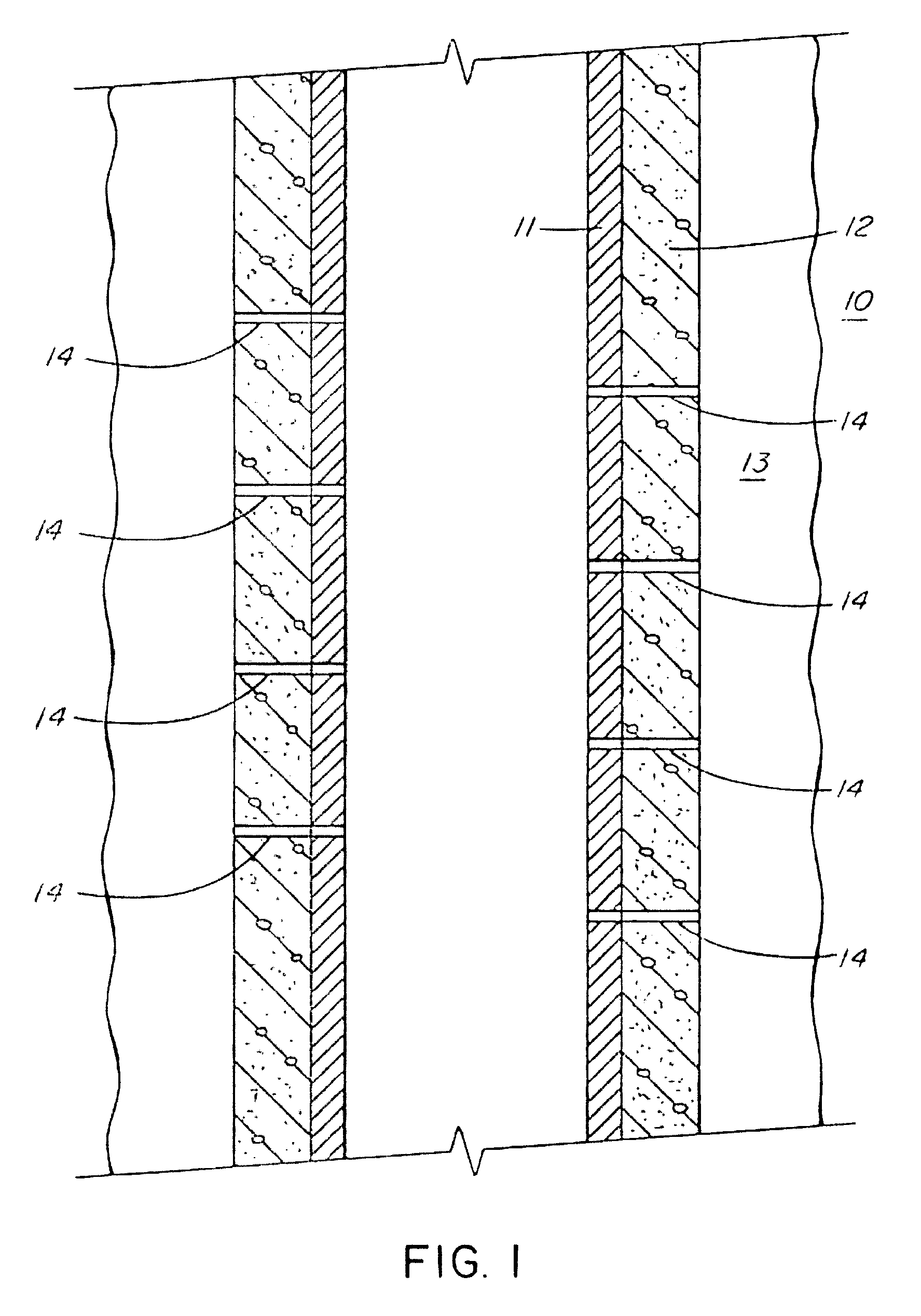
[0015] Referring now to the drawings, an oil or gas well is generally illustrated at 10 in FIG. 1 with the production casing 11 being cemented in by cement 12 which seals the production casing from the formation of interest which is an oil or gas bearing formation generally illustrated at 13.

[0016] Perforations 14 have been formed in the casing 11 and extend into the formation of interest 13.

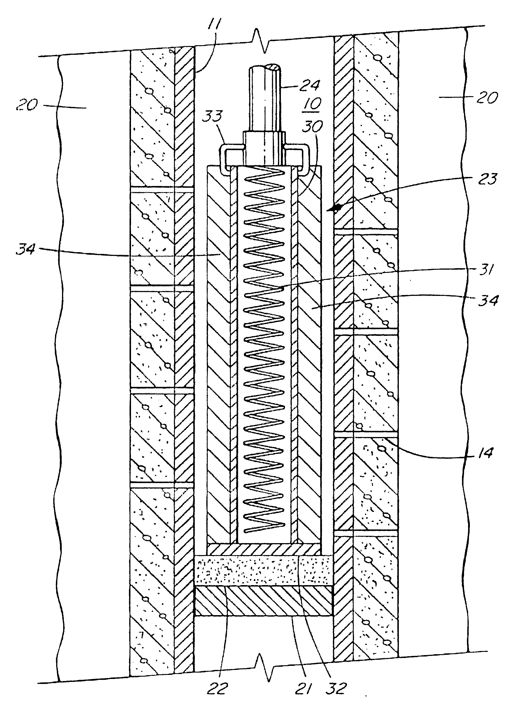
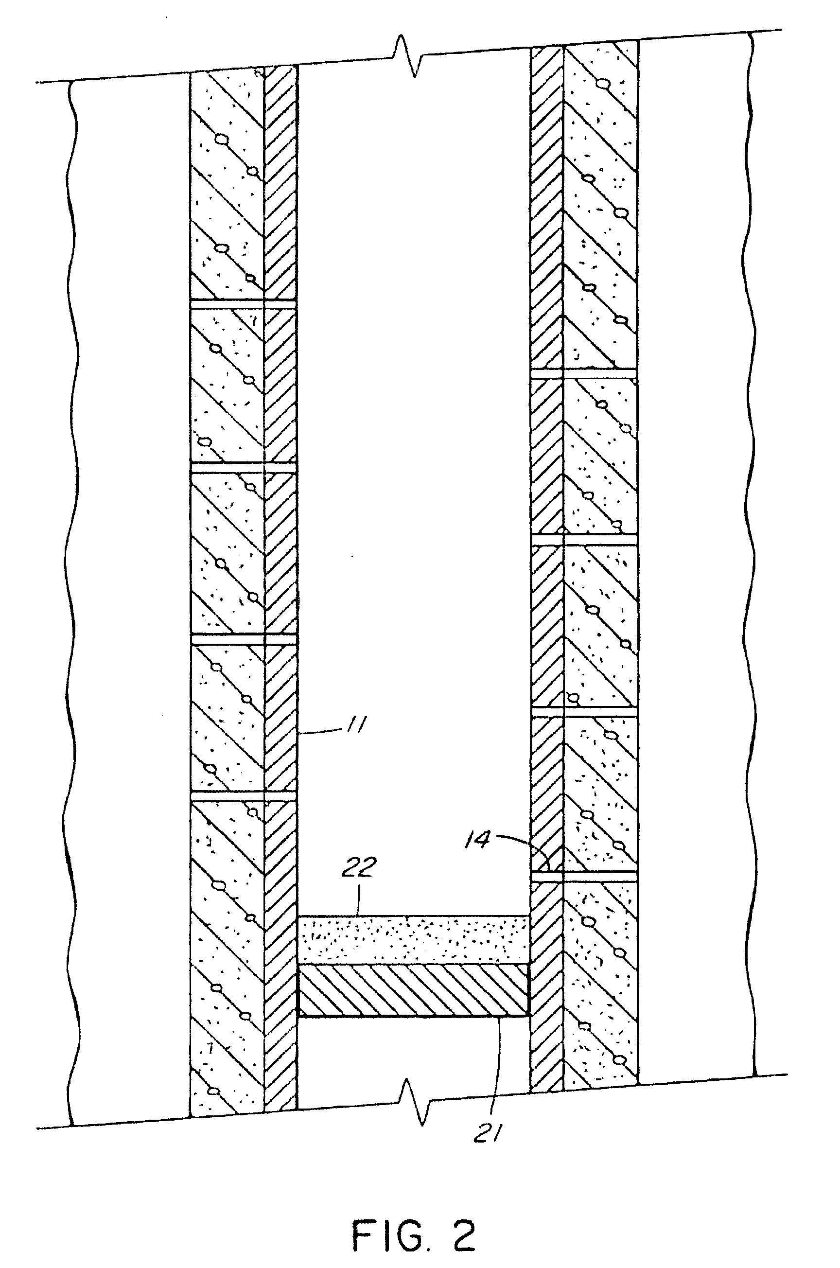
[0017] It is desired to plug the perforations 14 and to terminate flow from the formation 13 through the perforations 14 and into the casing 11. To do so, a retrievable bridge plug 21 is set in the casing 11 below the lowest one of the perforations 14 as illustrated in FIG. 2. The bridge plug 21 is formed within the casing 11 using wire line procedure which is known. A volume of sand 22 is then dumped into the casing 11 and on top of the bridge plug 21. The thickness of the sand layer 22 should extend upwardly to a position just below the lowermost one of the perforations of interest 14.

[0018...


PUM

PropertyMeasurementUnit
thermally conductiveaaaaaaaaaa
fusibleaaaaaaaaaa
temperatureaaaaaaaaaa

Abstract

Apparatus and method for plugging perforations in an oil or gas well. A bridge plug is formed in the casing below the perforations. A heating tool and a fusible alloy adjacent the heating tool is lowered into the well to a position above the bridge plug and adjacent the perforations. Heat is applied to melt the fusible alloy and pressure is applied to the molten material to force it through the perforations. The heating operation is terminated to allow the molten material to solidify and plug the perforations.

Description

CROSS-REFERENCE TO RELATED APPLICATION [0001] This application claims priority from U.S. Provisional Application Ser. No. 60 / 805,734 filed Jun. 24, 2006 entitled PERFORATION PLUGGING TOOL AND PROCEDURE (Spencer).INTRODUCTION [0002] This invention relates to method and apparatus for plugging perforations in an oil or gas well and, more particularly, to plugging an oil or gas well which utilizes a fusible alloy for plugging the perforations. BACKGROUND OF THE INVENTION [0003] In the oil and gas production industry, a perforated interval in the casing of the well is created to allow enhanced oil flow from the oil holding formation into the casing. The perforations are holes that extend from the inside of the well casing to the outside and are created by explosive shooting or other perforation techniques which techniques form no part of the present invention. [0004] Following the long use of the perforations for oil or gas flow into the casing, water flow becomes a problem. The water is...

Claims


Application Information

Patent Timeline
Patent Type & Authority Applications(United States)
IPC IPC(8): E21B33/13E21B36/04
CPCE21B29/10E21B36/00E21B33/138
Inventor SPENCER, HOMER L.
Owner SPENCER HOMER L
Why Eureka
Try Eureka