Actuator for controlling brake fluid pressure

a technology of brake fluid and actuator, which is applied in the direction of positive displacement liquid engines, machines/engines, braking systems, etc., can solve the problems of increasing the power consumption of the motor and and the excessive discharge volume of brake fluid, so as to reduce the size of the actuator and suppress the power consumption

Inactive Publication Date: 2008-02-28
ADVICS CO LTD
View PDF4 Cites 22 Cited by
  • Summary
  • Abstract
  • Description
  • Claims
  • Application Information

AI Technical Summary

Benefits of technology

[0006]It is therefore an object of the present invention to suppress the power consumption and reduce the size of an actuator in which a motor drives both a pump for a front wheel and a pump for a rear wheel.
[0008]Therefore, it is possible to suppress the power consumption of the motor and reduce the size of the actuator by reducing the volume of the brake fluid discharged from the second pump for the rear wheel.
[0015]In this case, a portion of the housing closer to the first surface than to the second surface is thick, and therefore it is easy to form a large conduit in the portion. Therefore, by forming the suction conduit in the portion, it is possible to make a radius of the suction conduit to be large and accordingly reduce a resistance force applied to the brake fluid flowing in the suction conduit.

Problems solved by technology

However, this results in an excessive discharge volume of brake fluid from the pump for the rear wheel.
The surplus' discharge volume increases the load of the motor, and accordingly raises the power consumption of the motor and the size of the actuator.

Method used


Image

  • Actuator for controlling brake fluid pressure
  • Actuator for controlling brake fluid pressure
  • Actuator for controlling brake fluid pressure

Examples


Embodiment Construction

[0023]An embodiment of the present invention will be described below with reference to the drawings.

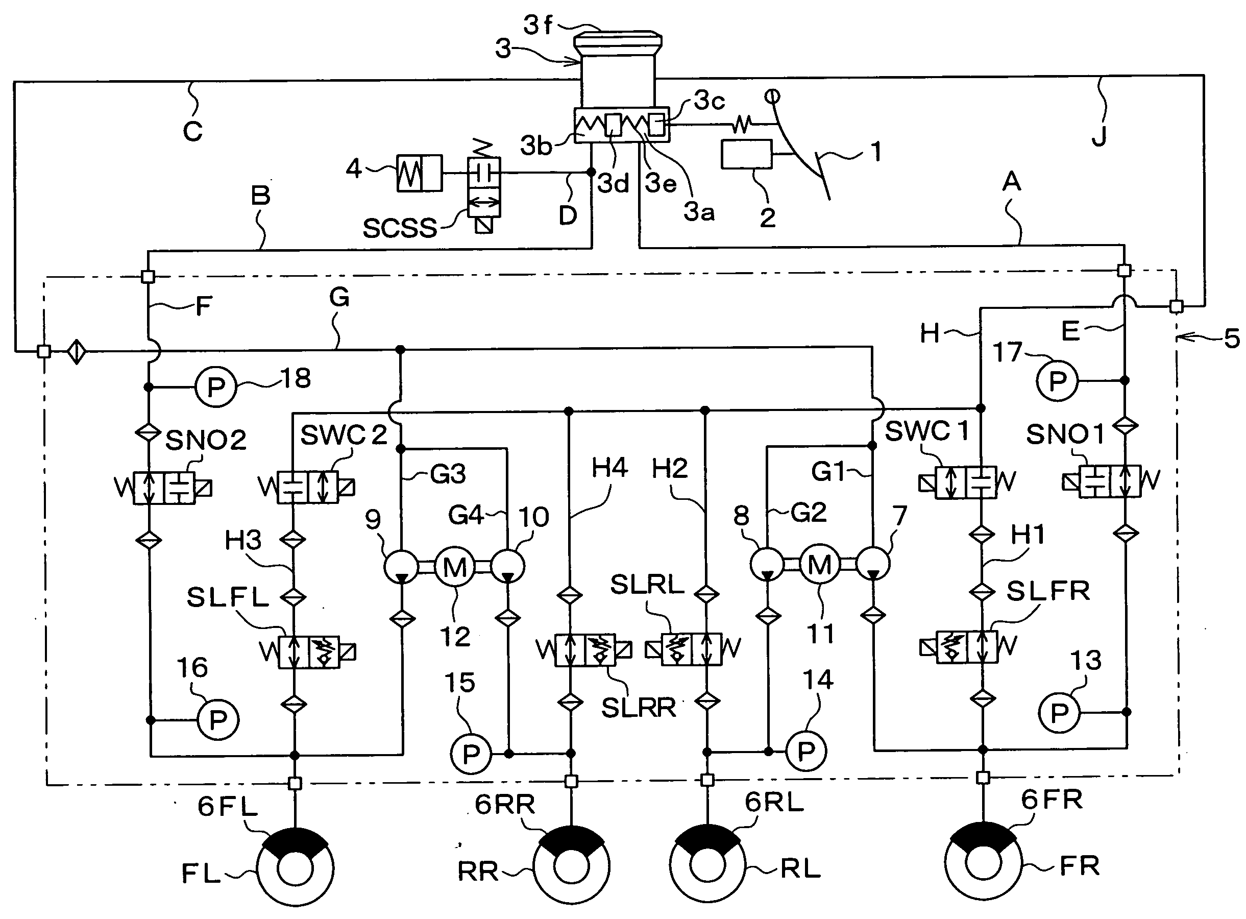
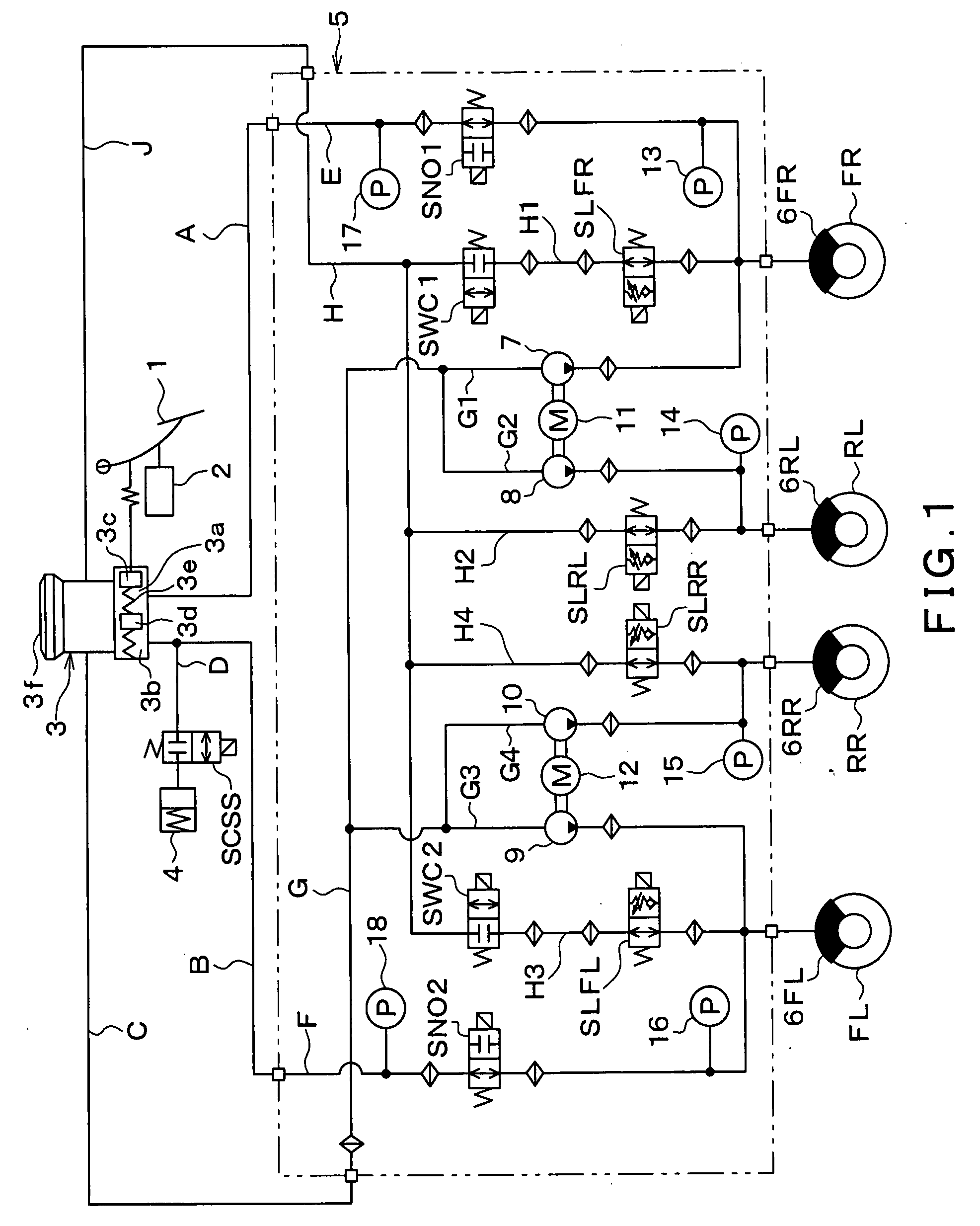
[0024]An actuator for controlling brake fluid pressures (hereinafter referred to as a brake fluid pressure control actuator) according to an embodiment of the present invention is applied to a vehicle with an X-type hydraulic circuit including two conduit systems, one of which serves the right front wheel and the left rear wheel of the vehicle and the other of which serves the left front wheel and the right rear wheel of the vehicle.

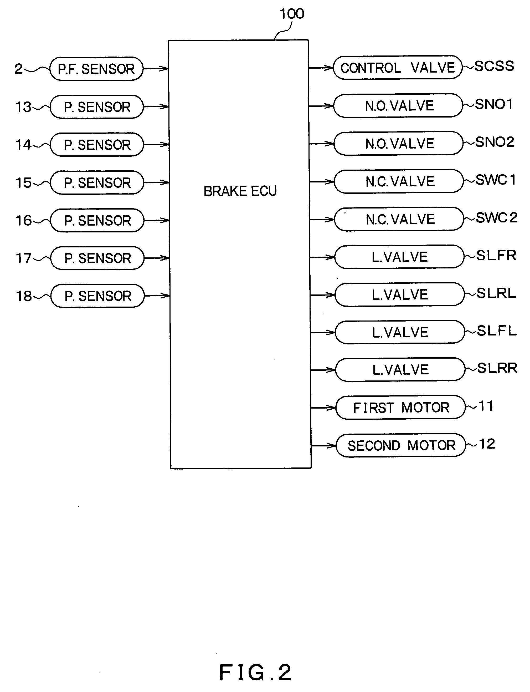
[0025]As shown in FIG. 1, the vehicle brake control device includes a brake pedal 1, a depression force sensor 2, a master cylinder (hereinafter referred to as an M / C) 3, a stroke control valve SCSS, a stroke simulator 4, the brake fluid pressure control actuator 5, and wheel cylinders (hereinafter referred to as W / Cs) 6FL, 6FR, 6RL, 6RR, as well as a brake ECU 100 shown in FIG. 2.

[0026]When the brake pedal 1, which is an example of a brake operating membe...


PUM


Abstract

An actuator installed in a vehicle controls brake fluid pressures applied respectively to a first wheel cylinder for a front wheel and a second wheel cylinder for a rear wheel. The actuator includes a first pump for the front wheel, a second pump for the rear wheel, and a motor for driving the first pump and the second pump. The first pump sucks brake fluid and discharges the brake fluid to the first wheel cylinder. The second pump sucks brake fluid and discharges the brake fluid to the second wheel cylinder. In addition, a discharge volume of the first pump is larger than a discharge volume of the second pump.

Description

CROSS REFERENCE TO RELATED APPLICATION[0001]This application is based on and incorporates herein by reference Japanese patent application No. 2006-225501 filed on Aug. 22, 2006.FIELD OF THE INVENTION[0002]The present invention relates to an actuator for controlling brake fluid pressures applied to wheel cylinders.BACKGROUND OF THE INVENTION[0003]In an actuator for controlling brake fluid pressures, pumps are housed which suck and discharge brake fluid in order to supply each of wheel cylinders with brake fluid. A conventional art (for example, JP H11-208440A) is known that a motor controls both one of the pumps for a front wheel and another one of the pumps for a rear wheel. In this art, the pump for the front wheel discharges as much brake fluid as the pump for the rear wheel.[0004]Because a volume of brake fluid used by a wheel cylinder for the front wheel is larger than that used by a wheel cylinder for the rear wheel, it is necessary in this art that the discharge volumes of the...

Claims


Application Information

Patent Timeline
Patent Type & Authority Applications(United States)
IPC IPC(8): B60T8/34F04B49/08
CPCB60T8/26B60T8/4081B60T8/368
Inventor SAKAI, MORIHARU
Owner ADVICS CO LTD
Why Eureka
Try Eureka