Thermal controlling method, magnetic field generator and MRI apparatus

a magnetic field generator and controlling method technology, applied in the direction of instruments, furniture, measurements using nmr, etc., can solve the problem of extremely high cost of magnets

Inactive Publication Date: 2008-02-28
GE MEDICAL SYST GLOBAL TECH CO LLC
View PDF12 Cites 196 Cited by
  • Summary
  • Abstract
  • Description
  • Claims
  • Application Information

AI Technical Summary

Benefits of technology

[0023]According to the invention related to one aspect, the thermal controlling method is a method for controlling a temperature of a magnetic field generator having a pair of disc-shaped permanent magnets whose magnetic poles opposite in polarity to each other are opposed to each other with spacing defined therebetween, and a yoke which forms return passes for magnetic fluxes of the permanent magnets, comprising the steps of raising the temperature from a room temperature to a temperature higher than the room temperature, maintaining the temperature higher than the room temperature, lowering the temperature from the temperature higher than the room temperature to the room temperature, and making temperature characteristics of the permanent magnets reversible. It is therefore possible to implement a thermal controlling method which makes reversible the temperature characteristic of a magnetic field generator using permanent magnets small in Hcj.
[0024]According to the invention related to another aspect, the magnetic field generator is a magnetic field generator comprising a pair of disc-shaped permanent magnets whose magnetic poles opposite in polarity to each other are opposed to each other with spacing defined therebetween, and a yoke which forms return passes for magnetic fluxes of the permanent magnets, wherein each of the permanent magnets includes a first portion relatively large in demagnetization, which is co

Problems solved by technology

However, such a magnet becomes extremely expensive becaus

Method used


Image

  • Thermal controlling method, magnetic field generator and MRI apparatus
  • Thermal controlling method, magnetic field generator and MRI apparatus
  • Thermal controlling method, magnetic field generator and MRI apparatus

Examples


Embodiment Construction

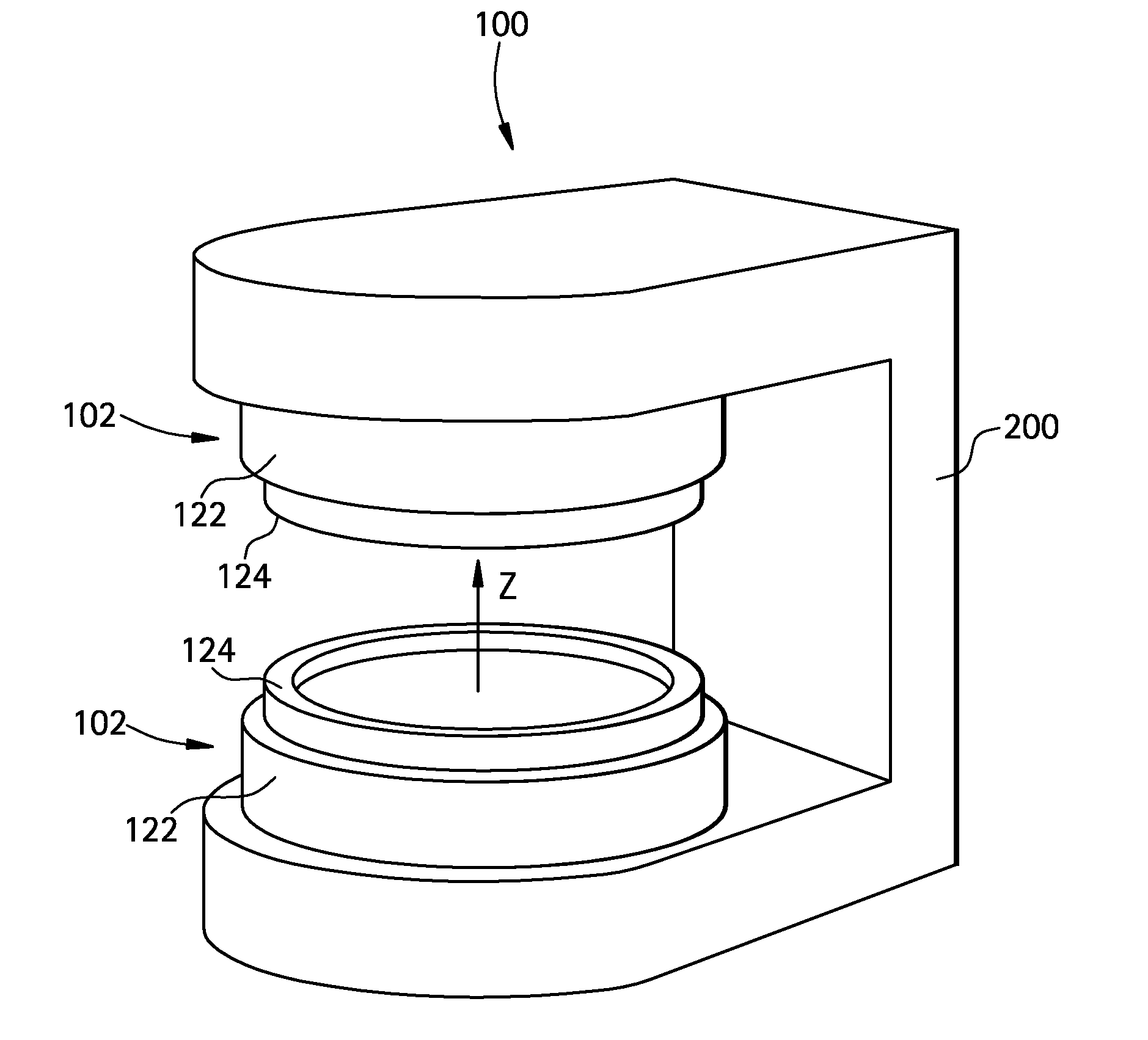
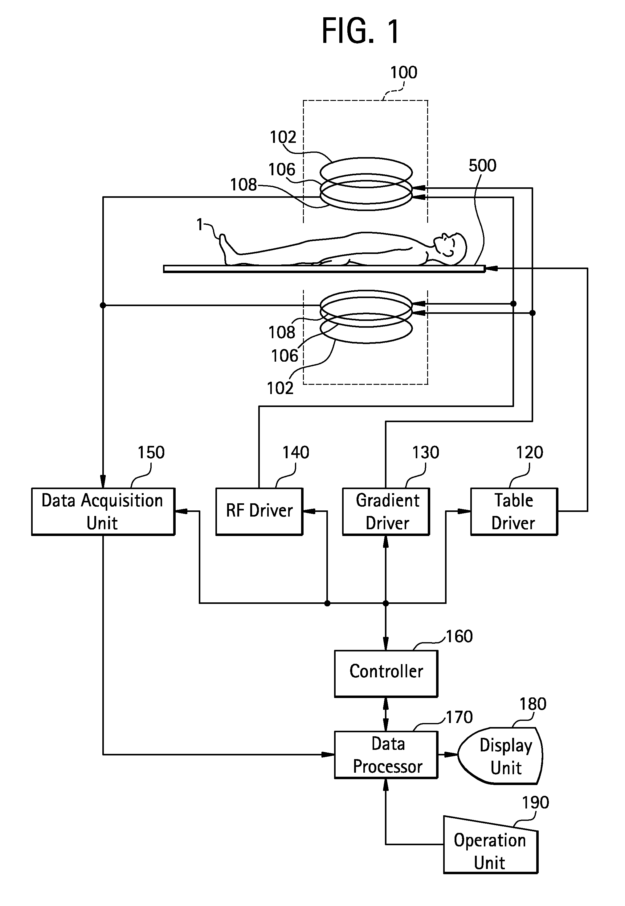
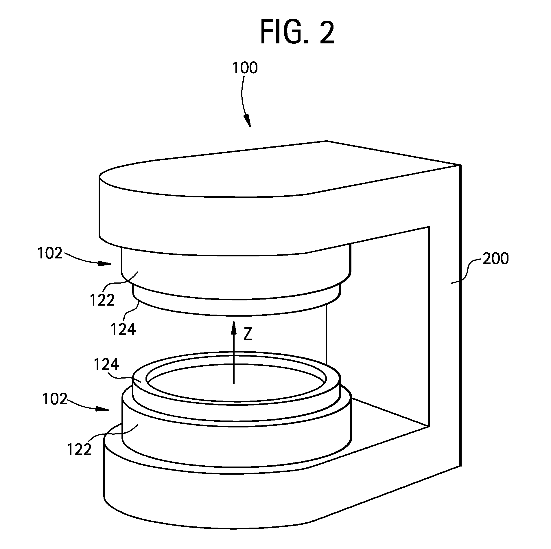
[0036]A best mode for carrying out the invention will hereinafter be explained in detail with reference to the figures. Incidentally, the present invention is not limited to the best mode for carrying out the invention. A block diagram of an MRI apparatus is shown in FIG. 1. The present apparatus is one example of the best mode for carrying out the invention. One example of the best mode for carrying out the invention related to the MRI apparatus is shown according to the construction of the present apparatus.

[0037]As shown in FIG. 1, the present apparatus has a magnetic field generator 100. The magnetic field generator 100 has main magnetic field magnet units 102, gradient coil units 106 and RF (radio frequency) coil units 108.

[0038]Any of the main magnetic field magnet units 102, gradient coil units 106 and RF coil units 108 comprises paired ones opposed to one another with a space interposed therebetween. Further, any of them has a substantially disc shape and is placed with its ...


PUM


Abstract

With a view toward implementing a thermal controlling method for making reversible a temperature characteristic of a magnetic field generator using permanent magnets small in Hcj, a magnetic field generator whose temperature characteristic is reversible, using permanent magnets small in Hcj, and an MRI apparatus provided with such a magnetic field generator, there is provided a method for controlling the temperature of a magnetic field generator having a pair of disc-shaped permanent magnets whose magnetic poles opposite in polarity to each other are opposed to each other with spacing defined therebetween, and a yoke that forms return passes for magnetic fluxes of the permanent magnets, comprising the steps of raising the temperature from room temperature to a temperature higher than the room temperature, maintaining the temperature higher than the room temperature, and lowering the temperature from the temperature higher than the room temperature to the room temperature, whereby the temperature characteristics of the permanent magnets are made reversible.

Description

CROSS REFERENCE TO RELATED APPLICATIONS[0001]This application claims the benefit of Chinese Application No. 200610121228.1 filed Jul. 14, 2006.BACKGROUND OF THE INVENTION[0002]The present invention relates to a thermal controlling method, a magnetic field generator and an MRI (Magnetic Resonance Imaging) apparatus, and more specifically to a method for controlling the temperature of a permanent magnet-type magnetic field generator, a permanent magnet-type magnetic field generator, and an MRI apparatus provided with such a magnetic field generator.[0003]An MRI apparatus acquires a magnetic resonance signal under a magnetic field generated by a magnetic field generator and reconstructs an image, based on the magnetic resonance signal. As one apparatus of the magnetic field generator, there is known one using permanent magnets. A pair of disc-shaped permanent magnets whose magnetic poles opposite in polarity to each other are opposed to each other with spacing defined therebetween is u...

Claims


Application Information

Patent Timeline
IPC IPC(8): G01R33/44F27D19/00H01F7/02
CPCG01R33/3804H01F7/0278G01R33/383G01R33/3806
Inventor TAN, FENGSHUNSHEN, WEIJUNHUA, YIHELIU, LIANG
Owner GE MEDICAL SYST GLOBAL TECH CO LLC
Why Eureka
Try Eureka