Information Display Apparatus and Navigation Apparatus

a technology of information display and navigation apparatus, which is applied in the direction of static indicating devices, navigation instruments, instruments, etc., can solve the problems of difficult to view projected information, so as to reduce the visibility of the external world via the combiner

Inactive Publication Date: 2008-02-28
PIONEER CORP
View PDF7 Cites 62 Cited by
  • Summary
  • Abstract
  • Description
  • Claims
  • Application Information

AI Technical Summary

Benefits of technology

[0006] The present invention is devised in consideration of the above problem, and its object is to provide an information display apparatus and a navigation apparatus such as a head-up display which are capable of realizing enlargement of a display apparatus such as a combiner, securing safety and improving visibility from users. Means for Solving the Problems

Problems solved by technology

However, in such a head-up display, since the emitted light from the projector and external light are combined by the combiner, when the luminance of the external light is heightened, there is the possibility of difficulty in viewing information projected onto the combiner.
For example, when the head-up display is tried to be used in the daytime where the irradiation amount of natural light is large, there is the possibility of difficulty in viewing projected information due to an influence of the natural light.
Further, even during evening hours, for example, there is the possibility of difficulty in viewing projected information due to an influence of a headlight of an oncoming car or the like.

Method used


Image

  • Information Display Apparatus and Navigation Apparatus
  • Information Display Apparatus and Navigation Apparatus
  • Information Display Apparatus and Navigation Apparatus

Examples


first embodiment

[1.3] MODIFIED EXAMPLE OF FIRST EMBODIMENT

(1) Modified Example 1

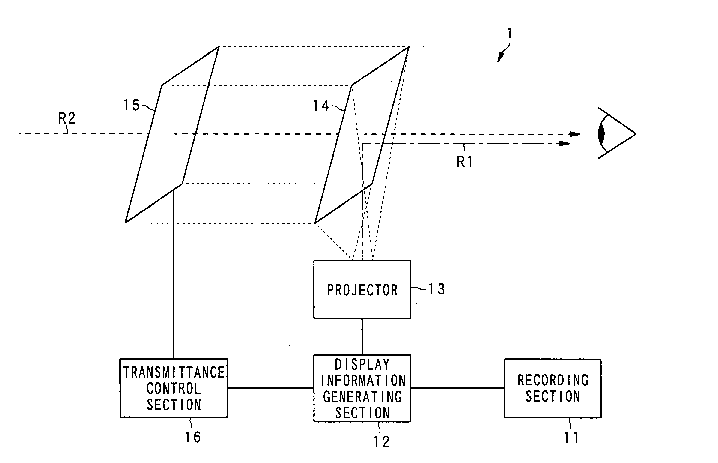
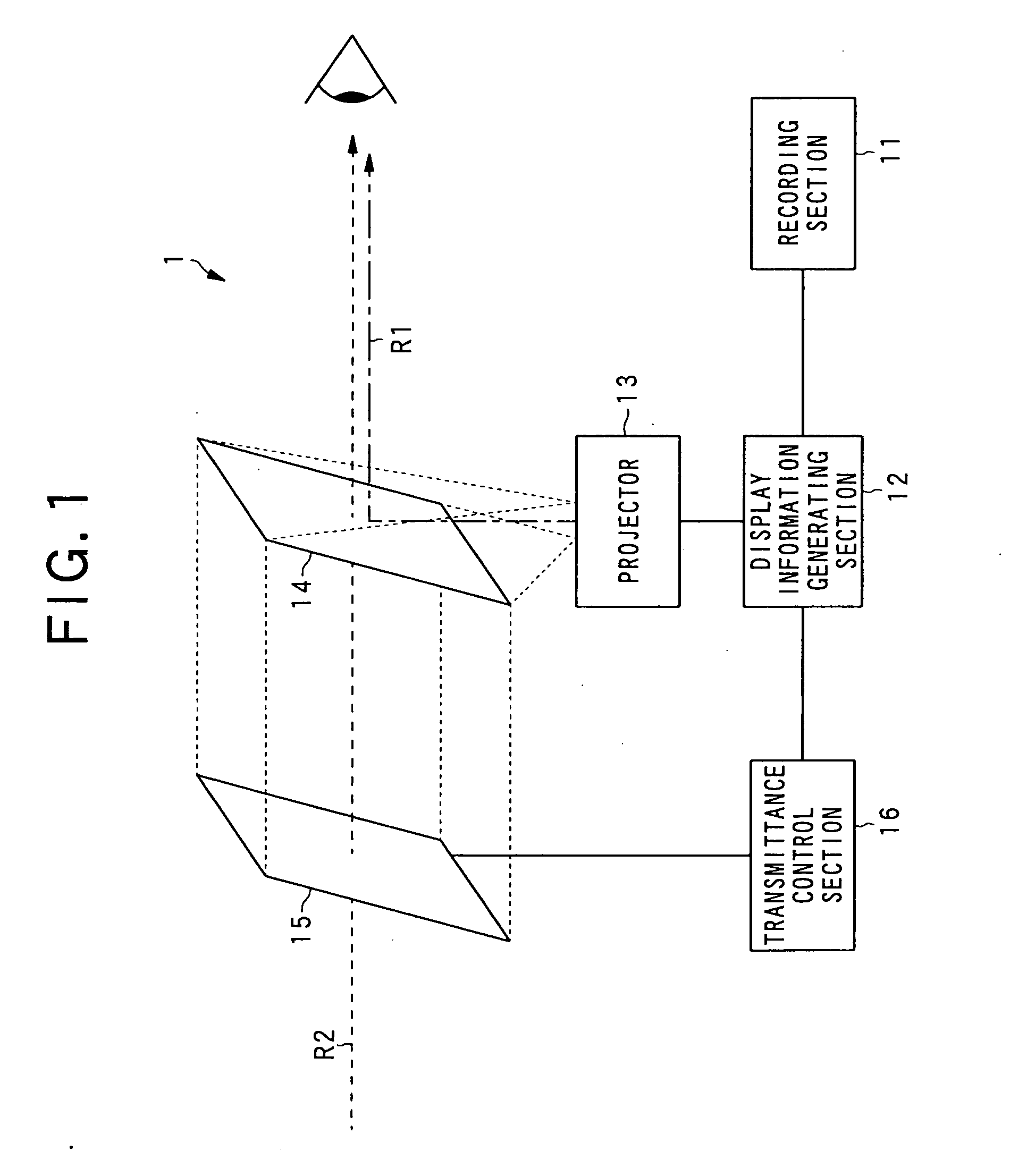
[0071] In the information display apparatus I according to the first embodiment, the combiner 14 and the light control panel 15 are constituted integrally. However, the combiner 14 and the light control panel 15 are formed separately, and can be arranged with a gap being provided therebetween.

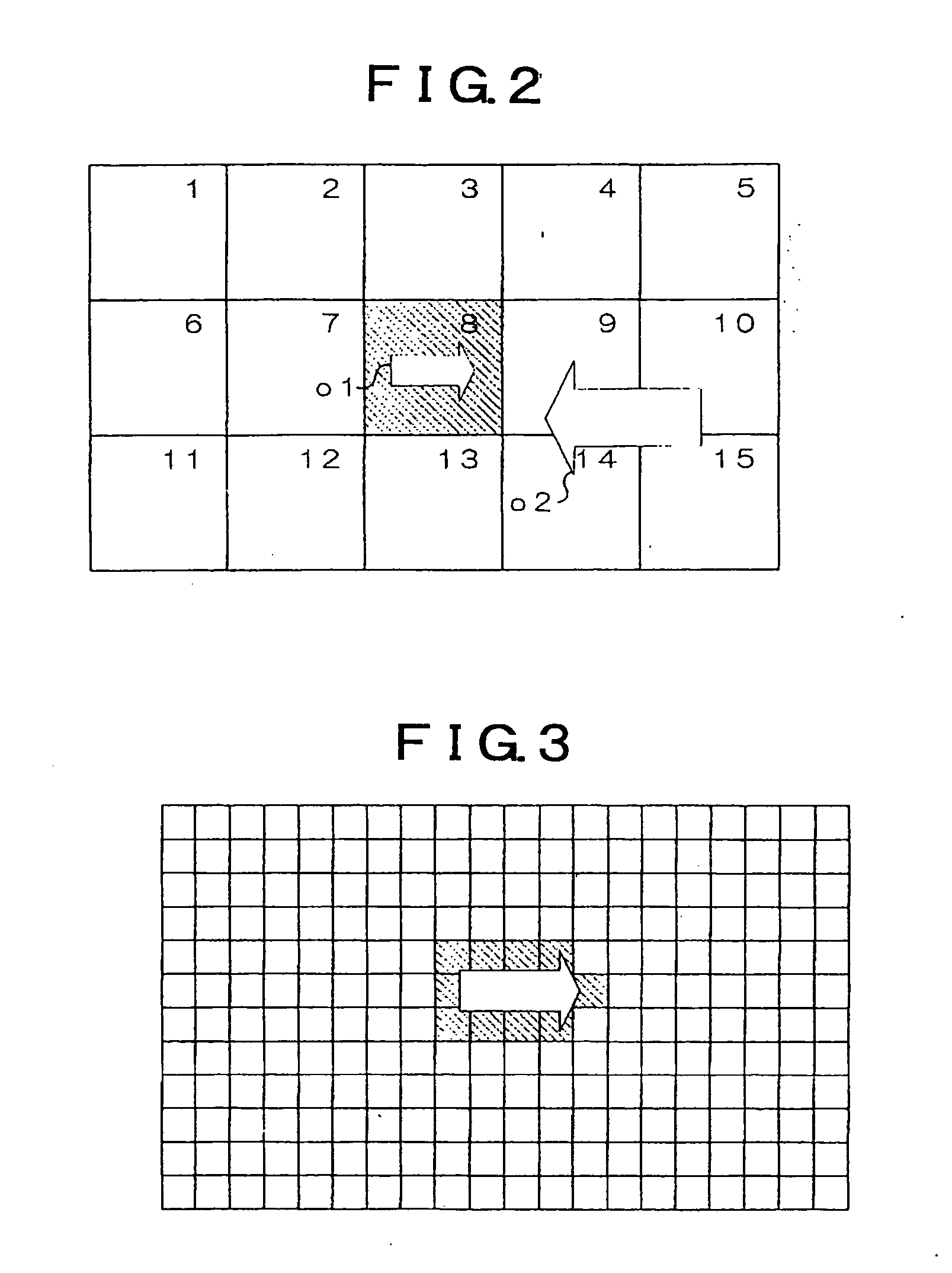
[0072] When such a constitution is adopted, it is necessary to generate the xX translation table while an attention is being paid to the following point in comparison with the integral constitution. As shown in FIG. 7, the case where the object o3 projected onto the combiner 14 is viewed from the user's viewing position P is considered. In FIG. 7, for easy understanding, only y and Y axial directions in the coordinate (x, y) of the combiner 14 and the coordinate (X, Y) of the light control panel 15 are shown.

[0073] In the case of FIG. 7, the coordinate group (y1 to y2) corresponding to the display position of the object o3 on th...

example 2

(2) Modified Example 2

[0076] Like the modified example 1, when the combiner 14 and the light control panel 15 are arranged with a gap, in order to match the coordinate (x, y) on the combiner 14 with the coordinate (X, Y) on the light control panel 15, it is necessary that the user's viewing position P does not greatly fluctuate. Therefore, when the combiner 14 and the light control panel 15 are provided, for example, to the windshield of a vehicle and are viewed from a driver's seat, no problem arises, but when the user's viewing position greatly fluctuates, both the coordinates occasionally do not match with each other.

[0077] When the apparatus is used under such an environment, the following methods should be adopted.

[0078] On the condition that the user's viewing position P changes, the corresponding relationship between the coordinate (x, y) on the combiner 14 and the coordinate (X, Y) on the light control panel 15 in the case of viewing from respective positions to be the vie...

example 3

(3) Modified Example 3

[0086]FIG. 9 illustrates a constitution of the information display apparatus I2 according to this modified example. In FIG. 9, the elements similar to those in FIG. 1 are designated by the same reference symbols. Therefore, the elements designated by the same reference symbols as those shown in FIG. 1 have the same constitutions as those in the first embodiment and perform the same operations unless otherwise specified.

[0087] The information display apparatus 12 according to the first embodiment adopts the constitution such that the information to be given to the user, namely, the object is projected by using the combiner 14 and the projector 13. On the contrary, in the information display apparatus 12 according to this modified example, a display panel 17 is provided instead of the comber 14 and the projector 13, and various objects are tried to be displayed on the display panel 17.

[0088] The display panel 17 is composed of a self-luminous type display appar...


PUM


Abstract

In an information display apparatus such as a head-up display, while safety is being secured, visibility from a user is improved. Image data having an object such as an arrow showing an advancing direction or a road sign drawn on it are generated as information to be given to the user by a display information generating section 12 and is output to a projector 13. When a light beam R1 corresponding to the image data is emitted from the projector 13 to a combiner 14, reflected light of the light beam R1 and transmitted light of external light R2 are combined in the combiner 14, so as to be viewed by the user. At this time, the display information generating section 12 outputs coordinate values showing a display position of the object to a transmittance control section 16, and the transmittance control section 16 specifies a display region of the object based on the coordinate values, and reduces the transmittance in the specified region of the light control panel 15 so as to reduce a transmitting amount of the external light R2.

Description

TECHNICAL FIELD [0001] The present invention relates to an information display apparatus which displays various information to be presented to users, and particularly relates to a see-through type information display apparatus which overlaps various information on a real landscape viewed by users so as to display them. BACKGROUND ART [0002] Conventionally, for example, in mobile objects such as vehicles and airplanes, so-called head-up displays, which present various information such as texts and speedometers showing progression speed to drivers through windshields, are put to practical use. A representative example of such head-up displays is such that a light beam is emitted from a projecting apparatus such as a projector to a combiner composed of a half mirror or HOE (Holographic Optical Element), and various information is presented to a user by using reflected light from the combiner. [0003] However, in such a head-up display, since the emitted light from the projector and exte...

Claims


Application Information

Patent Timeline
Patent Type & Authority Applications(United States)
IPC IPC(8): G09G5/00B60K35/00G01C21/00G01C21/36G02B27/00G02B27/01G02B27/02G08G1/0969G09B29/00G09B29/10G09G3/20G09G3/34
CPCG01C21/36G02B27/01G02B2027/0118G09G2300/08G08G1/0969G09B29/108G09G3/34G02B2027/014
Inventor YANAGISAWA, TAKUMA
Owner PIONEER CORP
Why Eureka
Try Eureka