Display device

a display device and display technology, applied in static indicating devices, non-linear optics, instruments, etc., can solve the problems of increasing frame area and wiring distance, affecting the display effect, so as to reduce the frame area and improve the effect of functional efficiency and good design

Active Publication Date: 2008-02-28
PANASONIC LIQUID CRYSTAL DISPLAY CO LTD +1
View PDF5 Cites 63 Cited by
  • Summary
  • Abstract
  • Description
  • Claims
  • Application Information

AI Technical Summary

Benefits of technology

[0020]According to the present invention, since it is possible to reduce the frame area in the display device having ...

Problems solved by technology

Although the section enclosing the image display area, i.e., a frame section is an area required for the display operation, but is not particularly necessary for the user and is not desirable for the good design of the display.
Although the notebook-sized personal computers in an early stage include quite a large frame area, the area is quite small at present.
This likely results in co...

Method used


Image

  • Display device
  • Display device
  • Display device

Examples


first embodiment

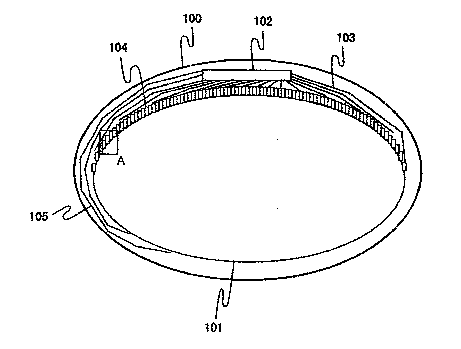
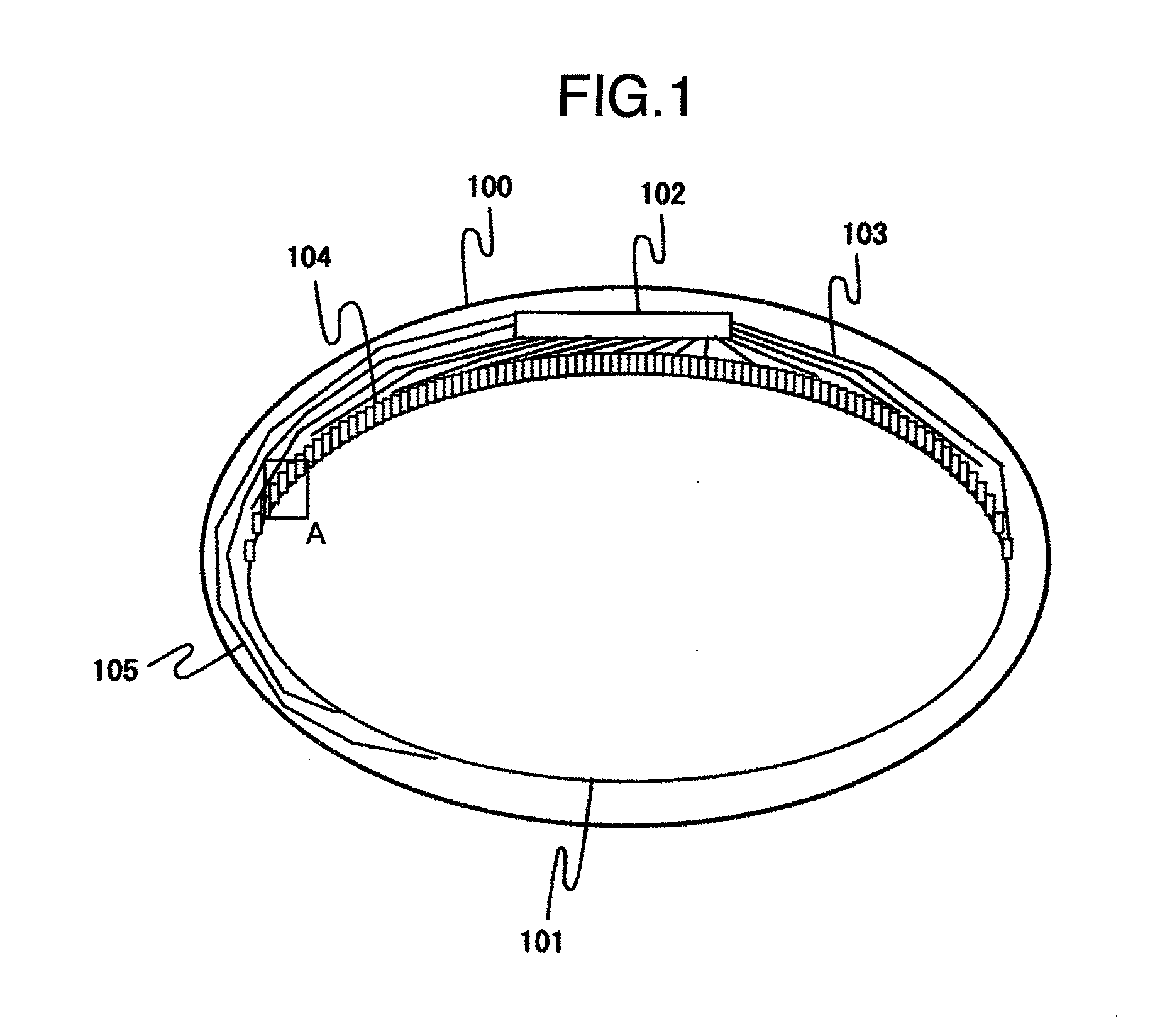
[0035]FIG. 1 shows an outline of a display device including a display section having a non-rectangular outer contour. Although the display section has an elliptic shape in FIG. 1, this is only an example of the display section having a non-rectangular outer contour.

[0036]In the display device 100 of FIG. 1 including a pixel display area 101, the area 101 has an elliptic outer contour and glass of the display device 100 has also an elliptic outer contour. The display device 100 in the first embodiment is an LCD device. Although not shown in FIG. 1, in the pixel display area 101, pixels are disposed in the form of an orthogonal matrix and signal wiring and scanning wiring are arranges also in the orthogonal configuration as in an ordinary LCD device. The signal wiring line is driven by a driver 102 via a signal wiring internal circuit 104 and a signal wiring leader line 103. The scanning wiring line is directly driven by the driver 102 via a scanning wiring leader line 105.

[0037]The d...

second embodiment

[0064]The second embodiment is substantially equal to the first embodiment excepting that the second invention is applied not only to the configuration of the signal wiring internal circuit, but also to that of the scanning wiring internal configuration.

[0065]FIG. 7 shows a magnified view of the curved arrangement section A of FIG. 1. This configuration employs the conventional signal wiring internal circuit 350 and a conventional scanning wiring internal circuit 450. Although the internal circuit 450 is smaller in the circuit area than the scanning wiring internal circuit module of the second embodiment, it is not possible to dispose the internal circuit 450 adjacent to the pixels, and the wiring is redundant. It is required to additionally arrange wiring to establish connection between the internal circuits 450. As a result, the frame area increases.

[0066]When compared with the elliptic pixel display area shown in FIG. 1, the configuration employing the scanning wiring internal ci...

third embodiment

[0075]FIG. 9 is a schematic diagram showing a display device including a display section having a non-rectangular outer contour. Although the display section has an elliptic shape, this is only an example of a display section having a non-rectangular outer contour.

[0076]In the display device 100 of FIG. 9, the image display area, i.e., a pixel display area 101 has an elliptic outer contour, and glass employed in the display device 100 has also an elliptic outer contour. The display device 100 in the embodiment is an LCD device. Although not shown in FIG. 9, the pixels are arranged in the form of an orthogonal matrix in the pixel display area 101. Also, signal wiring and scanning wiring are orthogonally arranged as in an ordinary LCD device.

[0077]The signal wiring is driven by the driver 102 via the signal wiring internal circuit 104 and the signal wiring leader line 103. The scanning wiring is driven by the driver 102 via the scanning wiring internal circuit 106 and the scanning wir...


PUM


Abstract

In a display device of built-in driver circuit type including a non-rectangular image display area, the frame area surrounding the display area is reduced and the wiring delay is reduced. The image display device includes a plurality of pixels arranged in an orthogonal matrix form, a plurality of scanning wiring lines connected to the plural pixels, a plurality of signal wiring lines connected to the plural pixels, the signal wiring lines being disposed to construct an orthogonal matrix form with the plural scanning wiring lines; signal wiring internal circuits for driving the plural signal wiring lines, and an image display area including a plurality of pixels, the image display area having a non-rectangular outer contour. The signal wiring internal circuits are separated from each other in an extending direction of the signal wiring lines in a unit of length of the pixel.

Description

BACKGROUND OF THE INVENTION[0001]The present invention relates to display devices such as a Liquid Crystal Display (LCD) device and an organic ElectroLuminescent (EL) display device and in particular, to a display device including a display section or area having a non-rectangular outer contour.[0002]Description will now be given of a conventional display device.[0003]Heretofore, there have been primarily employed Cathode Ray Tubes (CRT) devices as display devices. Recently, liquid crystal display devices of active matrix type which are planar display devices have been increasingly used due to space and power saving effects thereof. The LCD device is a display device using light transmission of a liquid crystal. The device does not emit light by itself, but controls light, i.e., backlight from a backlighting device through its states including a transmission state, an interruption state, and an intermediate state therebetween to thereby conducting gray scale or gradation display. Ad...

Claims


Application Information

Patent Timeline
IPC IPC(8): G09G3/20
CPCG02F1/13454G09G2300/0426G09G3/3611
Inventor YAMAMOTO, TSUNENORIOHARA, KENNAKAYOSHI, YOSHIAKIEDO, SUSUMUSAITO, HIROSHI
Owner PANASONIC LIQUID CRYSTAL DISPLAY CO LTD
Why Eureka
Try Eureka