
Image Processing Method, a Program of an Image Processing Method, a Recording Medium on Which a Program of an Image Processing Method is Recorded and an Image Processing Circuit

a technology of image processing and program, applied in the field of image processing circuit, can solve problems such as insufficient practice solution, and achieve the effect of detecting more accurately the presence of the area

Inactive Publication Date: 2008-02-28
SONY CORP
View PDF9 Cites 15 Cited by
  • Summary
  • Abstract
  • Description
  • Claims
  • Application Information

AI Technical Summary

Benefits of technology

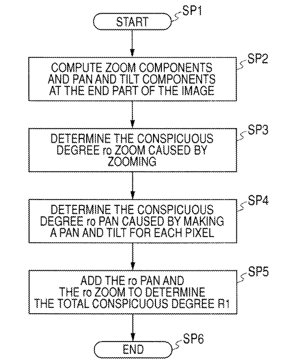
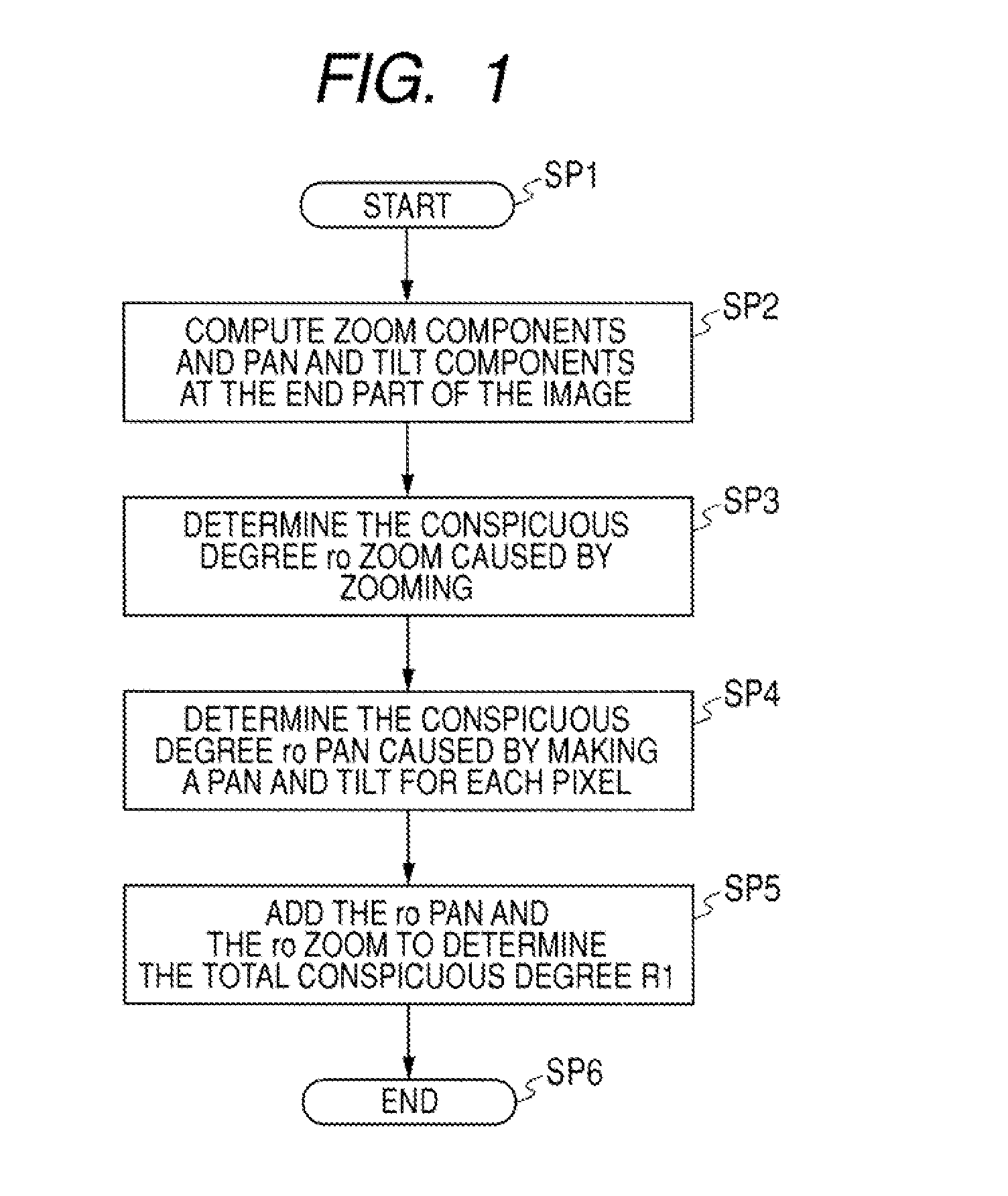
[0013]According to the configurations of an embodiment of the invention, even in the case in which the motion component caused by making a pan and tilt and the motion component caused by zooming operations exist together, the motion component caused by zooming operations is separated from the motion component caused by making a pan and tilt based on the representative value of the motion vector detected in the outer part of the screen, the motion component caused by zooming operations in each portion is detected from the motion component caused by zooming operations, and the detected result is used to detect the motion component caused by making a pan and tilt in each portion. Here, in the motion component caused by zooming operations in each portion that is thus detected, it can be said that the possibility of being the conspicuous area is higher as the portion is closer to the center of the screen, that is, as the portion has a smaller motion. In addition, in the motion component caused by making a pan and tilt in each portion, it can be said that the possibility of being the conspicuous area is higher in the portion the motion of the camera is more followed, that is, in the portion having a smaller motion. Accordingly, the conspicuous degree is determined that indicates the probability of being a conspicuous area from the motion component caused by zooming operations in each portion and the motion component caused by making a pan and tilt in each portion, and thus a conspicuous area can be detected more adequately than before.

Problems solved by technology

However, in the detection of a conspicuous area according to schemes before, there are still problems insufficiently solved in practice.

Method used


Image

  • Image Processing Method, a Program of an Image Processing Method, a Recording Medium on Which a Program of an Image Processing Method is Recorded and an Image Processing Circuit
  • Image Processing Method, a Program of an Image Processing Method, a Recording Medium on Which a Program of an Image Processing Method is Recorded and an Image Processing Circuit
  • Image Processing Method, a Program of an Image Processing Method, a Recording Medium on Which a Program of an Image Processing Method is Recorded and an Image Processing Circuit

Examples


embodiment 1

1. The Configuration of the Embodiment

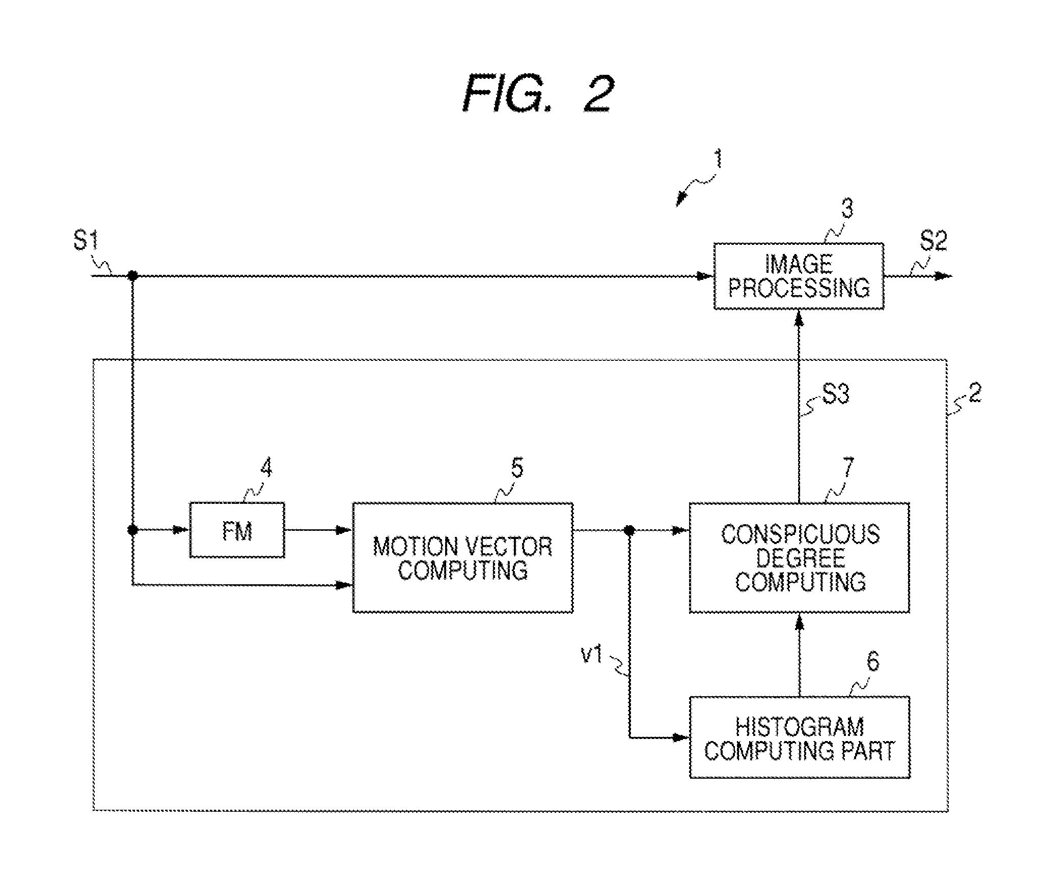
[0028]FIG. 2 shows a block diagram depicting an image processing circuit of embodiment 1 according to an embodiment of the invention. The image processing circuit 1 detects a conspicuous area from a video signal S1 by a conspicuous area detecting part 2, subjects the video signal S1 to image processing by an image processing part 3 based on the detected result of the conspicuous area, and outputs an output signal S2. In addition here, for example, for image processing in the image processing part 3, various schemes of image processing can be widely applied such as the generation of a key signal and a mask that extract a conspicuous area, and the correction of image quality predominantly for a conspicuous area.

[0029]In the conspicuous area detecting part 2, a frame memory (FM) 4 delays the video signal S1 by a period of a single frame and outputs it, and a motion vector computing part 5 subsequent thereto receives the video signal delayed by a si...

embodiment 2

[0071]FIG. 12 shows a block diagram depicting an image processing circuit of embodiment 2 according to an embodiment of the invention in contrast with FIG. 2. In an image processing circuit 11, the same configuration as that of the image processing circuit 1 described in FIG. 2 is designated the corresponding numerals and sings, omitting the overlapping descriptions.

[0072]In the image processing circuit 11, a conspicuous area detecting part 12 detects a conspicuous degree S4 of a video signal S1, and the conspicuous degree S4 is determined based on a threshold on an image processing part 13 side to generate a conspicuous area signal. The image processing part 13 subjects the video signal S1 to image processing based on the conspicuous area signal as similar to the image processing part 3 described in the embodiment 1.

[0073]In addition, as similar to the description in the embodiment 1, the conspicuous area detecting part 12 uses a representative value determined in a histogram compu...

embodiment 3

[0077]In addition, in the embodiments described above, the case is described in which the motion vector is simply used to detect the conspicuous area, but an embodiment of the invention is not restricted thereto. This scheme may be performed in which such a configuration is provided that a change in a scene is detected to stop detecting the motion vector, and a change in a scene is detected to hold the conspicuous degree at a value a single frame before. With this scheme, the conspicuous degree can be detected stably with no influence of the absence of the motion vector caused by finishing the operation of a camera, for example.

[0078]Moreover, in the embodiments described above, the case is described in which the motion vector is simply used to detect the conspicuous area, but an embodiment of the invention is not restricted thereto. This scheme may be performed in which the physical properties such as color, shapes, texture, spatial frequencies and others included in two dimensiona...


PUM


Abstract

An image processing method in which a video signal is processed to detect a conspicuous area which is thought that a camera person intends to shoot, the method includes the steps of: detecting a motion vector in each portion of the video signal; detecting a representative value that represents a motion in two places in an outer part of a screen; detecting a motion component caused by zooming operations from the representative value; detecting a conspicuous degree by zooming in which a motion component caused by zooming operations is detected in each portion of the video signal based on the motion component caused by zooming operations; correcting a motion vector; detecting a motion component caused by making a pan and tilt from the representative value; detecting a conspicuous degree caused by making a pan and tilt; and detecting a total conspicuous degree.

Description

CROSS REFERENCES TO RELATED APPLICATIONS[0001]The present invention contains subject matter related to Japanese Patent Application JP 2006-224911 filed in the Japanese Patent Office on Aug. 22, 2006, the entire contents of which being incorporated herein by reference.BACKGROUND OF THE INVENTION[0002]1. Field of the Invention[0003]The present invention relates to an image processing method, a program of an image processing method, a recording medium on which a program of an image processing method is recorded, and an image processing circuit, which, for example, can be used for adjusting the image quality of video signals. In the invention, motion vectors detected in the individual portions of imaging results are separated into components caused by zooming operations and components caused by making a pan and tilt, a conspicuous degree is detected that shows the probability of being a conspicuous area for each portion, and the conspicuous degree is detected in a comprehensive manner f...

Claims


Application Information

Patent Timeline
Patent Type & Authority Applications(United States)
IPC IPC(8): H04N5/14
CPCH04N5/232H04N23/695
Inventor YOKOYAMA, KAZUKIASANO, MITSUYASUUEDA, KAZUHIKO
Owner SONY CORP
Learn More