Intravascular filter monitoring

a filter and filter technology, applied in the field of intravascular filter monitoring, can solve the problems of difficult real-time monitoring of blood flow affecting the ability to readily monitor the flow of blood through an embolic protection filter, and occlusion of embolic protection filters

Inactive Publication Date: 2008-02-28
BOSTON SCI SCIMED INC
View PDF67 Cites 29 Cited by
  • Summary
  • Abstract
  • Description
  • Claims
  • Application Information

AI Technical Summary

Benefits of technology

[0006] The present invention relates generally to the field of intravascular filter monitoring. In an exemplary embodiment, an apparatus for monitoring blood flow across an intravascular device comprises an elongated member having a proximal end and a distal end, an intravascular device disposed about the elongated member proximal the distal end thereof, a first sensor adapted to measure blood flow or pressure proximal the intravascular device, and a second sensor adapted to measure blood flow or pressure distal the intravascular device. A control unit located outside of the patient's body may be used to determine the pressure drop across the intravascular device.

Problems solved by technology

Over time, the embolic protection filter may become occluded with the embolic debris, necessitating the removal and / or replacement of the filter from the vessel.
Although many techniques have been developed to monitor the flow of blood through a patient's body, real-time monitoring of blood flow through an embolic protection filter can often prove difficult.
One particular issue associated with fluoroscopic monitoring, however, is the ability to readily monitor the flow of blood through an embolic protection filter.
Since fluoroscopic monitoring may require as much as several minutes to perform, such techniques are not well suited for real-time monitoring of blood flow through an embolic protection filter.

Method used


Image

  • Intravascular filter monitoring
  • Intravascular filter monitoring
  • Intravascular filter monitoring

Examples


Embodiment Construction

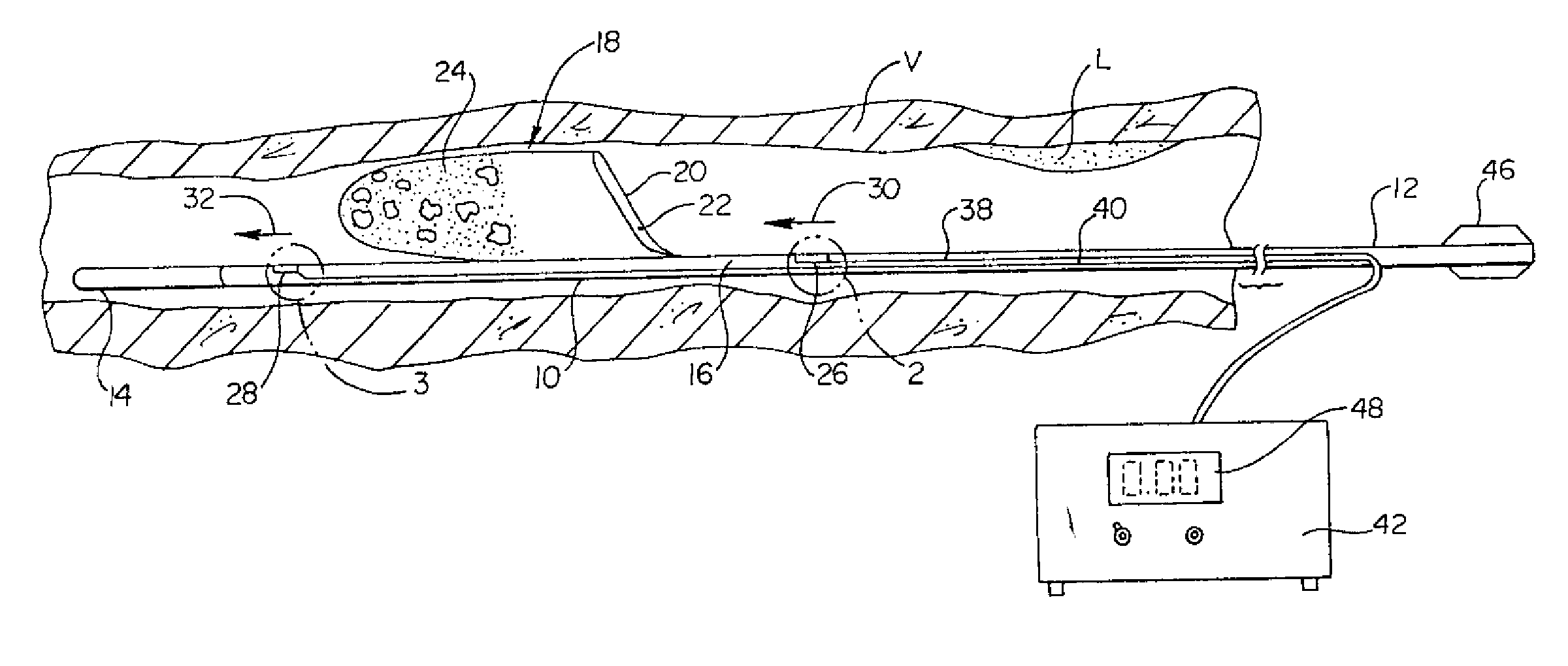
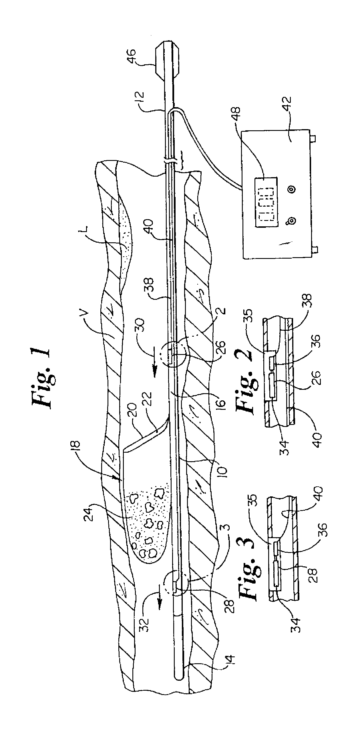
[0011] The following description should be read with reference to the drawings, in which like elements in different drawings are numbered in like fashion. The drawings, which are not necessarily to scale, depict selected embodiments and are not intended to limit the scope of the invention. Although examples of construction, dimensions, materials and manufacturing processes are illustrated for the various elements, those skilled in the art will recognize that many of the examples provided have suitable alternatives that may be utilized.

[0012]FIG. 1 is a plan view of an apparatus for monitoring the flow of blood through an intravascular device in accordance with an exemplary embodiment of the present invention. As shown in FIG. 1, an elongated member 10 is inserted into a patient's vessel V at least in part distal a lesion L. Elongated member 10 may be a tubular member having a proximal end 12, a distal end 14, and an inner lumen 16. An optional hub 46 attached to the proximal end 12...


PUM


Abstract

Devices and methods for monitoring the flow of blood through an intravascular device are disclosed. An apparatus for monitoring blood flow in accordance with an exemplary embodiment of the present invention includes an intravascular device coupled to an elongated member, a first sensor adapted to measure fluidic pressure proximal the intravascular device, a second sensor adapted to measure fluidic pressure distal the intravascular device, and a control unit for comparing the signals received from the first and second sensors to determine the pressure drop across the intravascular device.

Description

RELATED APPLICATIONS [0001] This application is a continuation application of U.S. application Ser. No. 10 / 306,288 filed Nov. 27, 2002.FIELD OF THE INVENTION [0002] The present invention relates generally to the field of intravascular filter monitoring. More specifically, the present invention pertains to devices and methods for monitoring the flow of blood through an embolic protection filter. BACKGROUND OF THE INVENTION [0003] Intravascular devices such as embolic protection filters are generally placed with the lumen of a blood vessel or artery to filter embolic debris dislodged during a therapeutic procedure such as percutaneous transluminal coronary angioplasty (PTCA), percutaneous extraction atherectomy, or stent delivery. To filter the dislodged embolic debris, an embolic protection filter can be placed distally of the therapeutic device (e.g. an angioplasty or atherectomy catheter) and deployed within the patient's vessel or artery. Over time, the embolic protection filter m...

Claims


Application Information

Patent Timeline
Patent Type & Authority Applications(United States)
IPC IPC(8): A61B5/026A61B5/0215A61F2/01
CPCA61B5/02156A61F2/013A61B5/02158
Inventor BROOME, THOMAS E.VRBA, ANTHONY C.ANDERSON, NARINCRANK, JUSTINHANSEN, JAMES G.LIN, HORNG-BANSMITH, MARK
Owner BOSTON SCI SCIMED INC
Why Eureka
Try Eureka