Spinal rod connector

Inactive Publication Date: 2008-02-28
ZIMMER SPINE INC
View PDF13 Cites 131 Cited by
  • Summary
  • Abstract
  • Description
  • Claims
  • Application Information

AI Technical Summary

Benefits of technology

[0008]This invention allows stable and secure locking of the rod against the connector and ultimately against each of the vertebrae held by the system. Fur

Problems solved by technology

The rigid connectors and clamps, however, can only accommodate support rods of either one specific diameter or a very small range of diameters.
In other cases, as in systems where the connectors are clamps, a good match between the connector rod opening and the surface of the rod is difficult to achieve.
In either situation, the connector does not adequately and securely hold the rod.
In the case of a point-and-continuous-curved surface contact, rotation of the rod with respect to the connect

Method used


Image

  • Spinal rod connector
  • Spinal rod connector
  • Spinal rod connector

Examples


Embodiment Construction

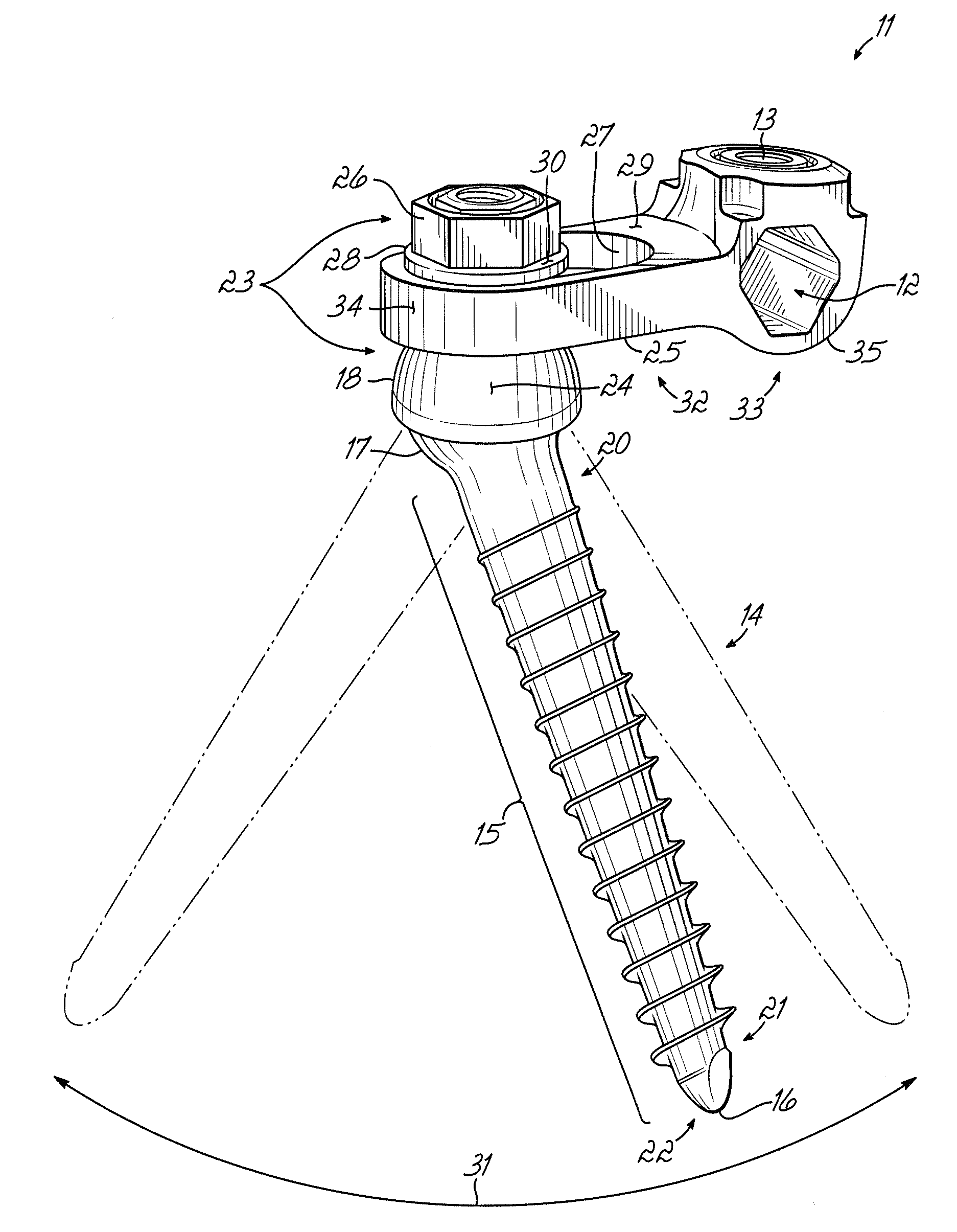
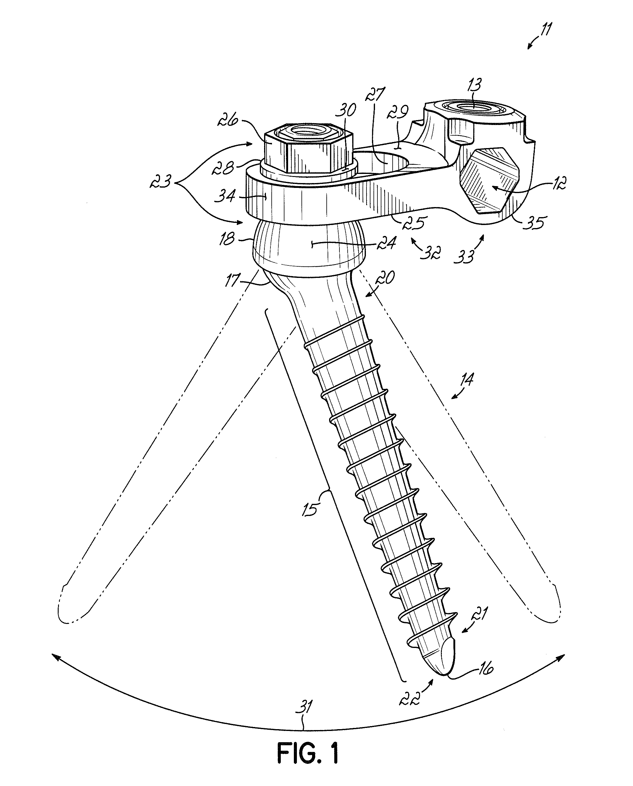
[0015]As shown in FIGS. 1-4 and in various embodiments, this invention is a system for fixation of human spinal column vertebrae through the use of a pre-shaped rod lo following a desired orientation of the column, a series of connectors 11 each having an aperture 12 allowing the rod lo to pass through them, fasteners such as set screws 13 securing each of the connectors 11 to the rod 10, and vertebrae-engaging anchors such as pedicle screws 14 securing each of the connectors 11 to a vertebra. This system, therefore, along with the associated method of spinal column fixation, achieves the goal of defining and preserving a desired relative spatial orientation of the vertebrae. While this invention is shown and described herein as a spinal fixation construct, it is readily applicable for use in other areas of the body such as the femur, tibia, fibula, humerus, ulna, radius, clavicle and others.

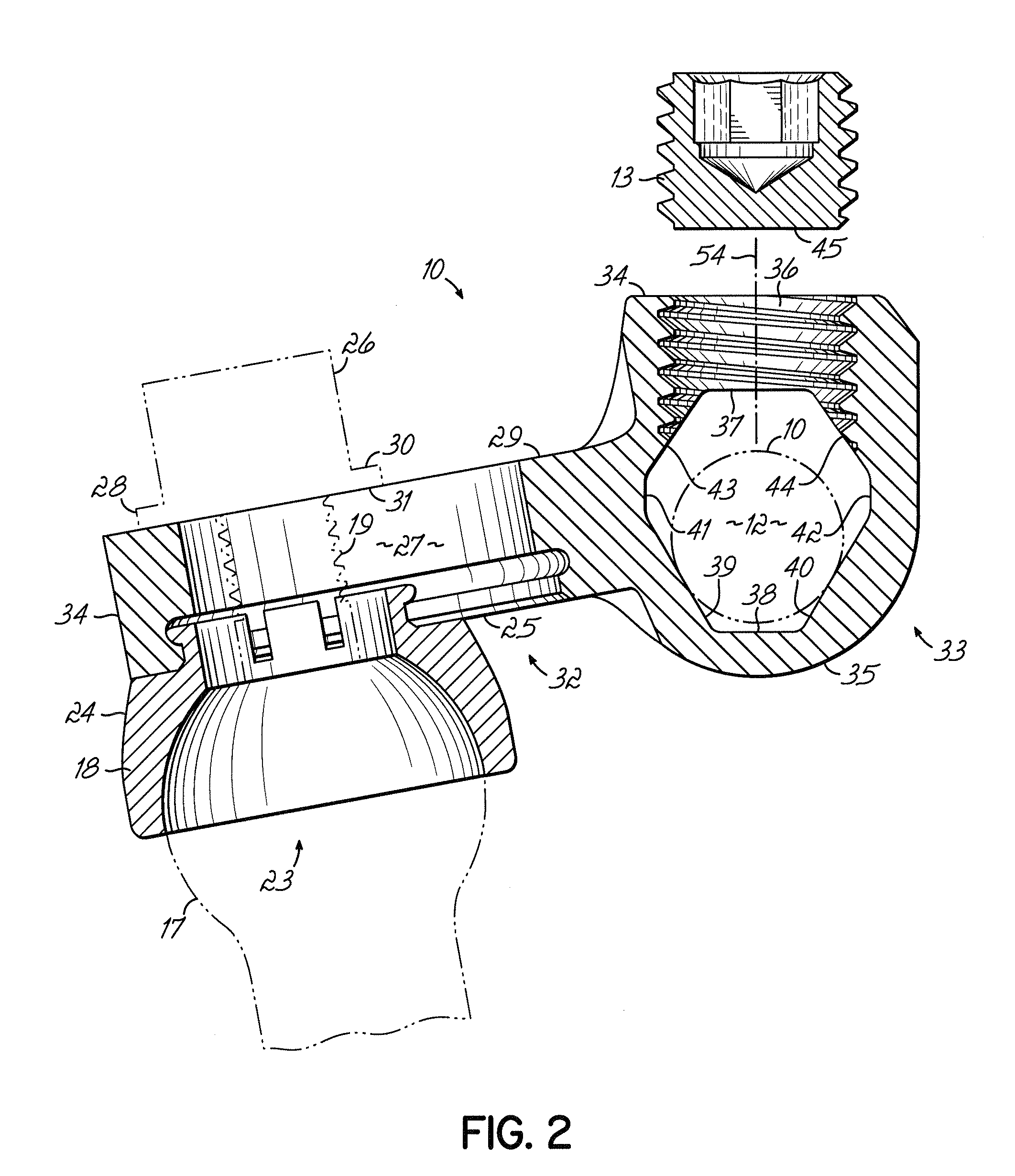
[0016]FIG. 1 shows one embodiment of this invention. A vertebral anchor such as a polyaxial ...


PUM


Abstract

A system and method for fixing the relative position of vertebrae in a human spinal column utilizes a unique connector, vertebral anchors and a longitudinal pre-shaped rod. The connector assemblies each have a pass-through aperture for the rod. Each of the apertures is shaped such that at least 3 surfaces of contact are created between a variety of rod sizes and each of the connectors, thereby allowing secure and stable holding of the rod with respect to the other system components and the vertebrae.

Description

BACKGROUND[0001]This invention relates to an apparatus and method for fixing the relative location of human vertebrae in a spinal column, and more specifically a spinal fixation construct utilizing vertebrae-engaging members, spine rods and connectors between the rod and engaging members.[0002]Surgically implanted spinal fixation systems are well known and are used to correct a variety of back structure problems, including those resulting from trauma as well as defective growth-related development of the spinal column. Apparatus to fix the relative location of human vertebrae are known and may consist of screws that are inserted into the vertebrae and are interconnected to a pre-shaped support rod by the use of rigid connectors or clamps.[0003]Some spinal fixation systems contain features that allow securing the support rod to the rigid connectors or clamps. The rigid connectors and clamps, however, can only accommodate support rods of either one specific diameter or a very small ra...

Claims


Application Information

Patent Timeline
IPC IPC(8): A61F2/30
CPCA61B17/7041A61B17/7035
Inventor VAIDYA, SHAILENDRATYAGI, KULDEEPHILLYARD, ANGELA L.
Owner ZIMMER SPINE INC
Why Eureka
Try Eureka