Aircraft thermal management system with reduced exhaust re-ingestion

a technology of thermal management system and gas turbine engine, which is applied in the direction of machines/engines, mechanical equipment, transportation and packaging, etc., can solve the problems of complicated effective thermal management, so as to enhance cooling airflow and minimize leakage and pressure loss

Inactive Publication Date: 2008-03-06
RAYTHEON TECH CORP
View PDF9 Cites 15 Cited by
  • Summary
  • Abstract
  • Description
  • Claims
  • Application Information

AI Technical Summary

Benefits of technology

[0010]The present invention therefore provides a thermal management cooling duct system which minimizes leakage and pressure losses yet enhances cooling airflow by resistance to re-ingestion of heated airflow from the heat exchanger during aircraft ground-idle operations.

Problems solved by technology

Tactical aircraft in particular place a premium on space such that systems that require cooling airflow are often packaged within the airframe in a manner which complicates effective thermal management thereof.
Such aircraft are required to operate in airport environments which further complicate effective thermal management such as high altitude and hot ambient temperature environments.
Still other operational conditions such as where a multitude of aircraft are stacked up on taxiways awaiting take-off in the mid-day sun still further complicates effective thermal management by raising the effective ambient temperature at a time when the aircraft can not be cooled by ingesting air provided by a ram scoop and the vehicle's forward velocity.
Conventional ducting and door arrangements often result in leakage and pressure losses in either or both operational conditions.
This intake and exhaust arrangement may result in the fan system re-ingesting heated exhaust air at close to 100% of the system's discharge temperature.
Thermal management may then be further complicated by the re-ingestion of exhausted air from the heat exchanger itself which has been further heated by solar loads as the air flows through the boundary layer on the aircraft upper surfaces.
In the case of fuel-air heat exchangers, still other operational conditions, such as low fuel tank levels, may further complicate thermal management because the fuel in the tank starts to heat up as warm, poorly cooled fuel is returned to the tank and mixes in with the balance of the fuel.
Various combinations of these adverse conditions may cause fuel tank temperatures to rise relatively quickly and surpass a limiting temperature such as the fuel tank seal allowable limits in the case of fuel systems, and bearing compartment lubrication temperature limits in the case of oil systems, and chemical degradation limits in the case of hydraulic systems.

Method used


Image

  • Aircraft thermal management system with reduced exhaust re-ingestion
  • Aircraft thermal management system with reduced exhaust re-ingestion
  • Aircraft thermal management system with reduced exhaust re-ingestion

Examples


Embodiment Construction

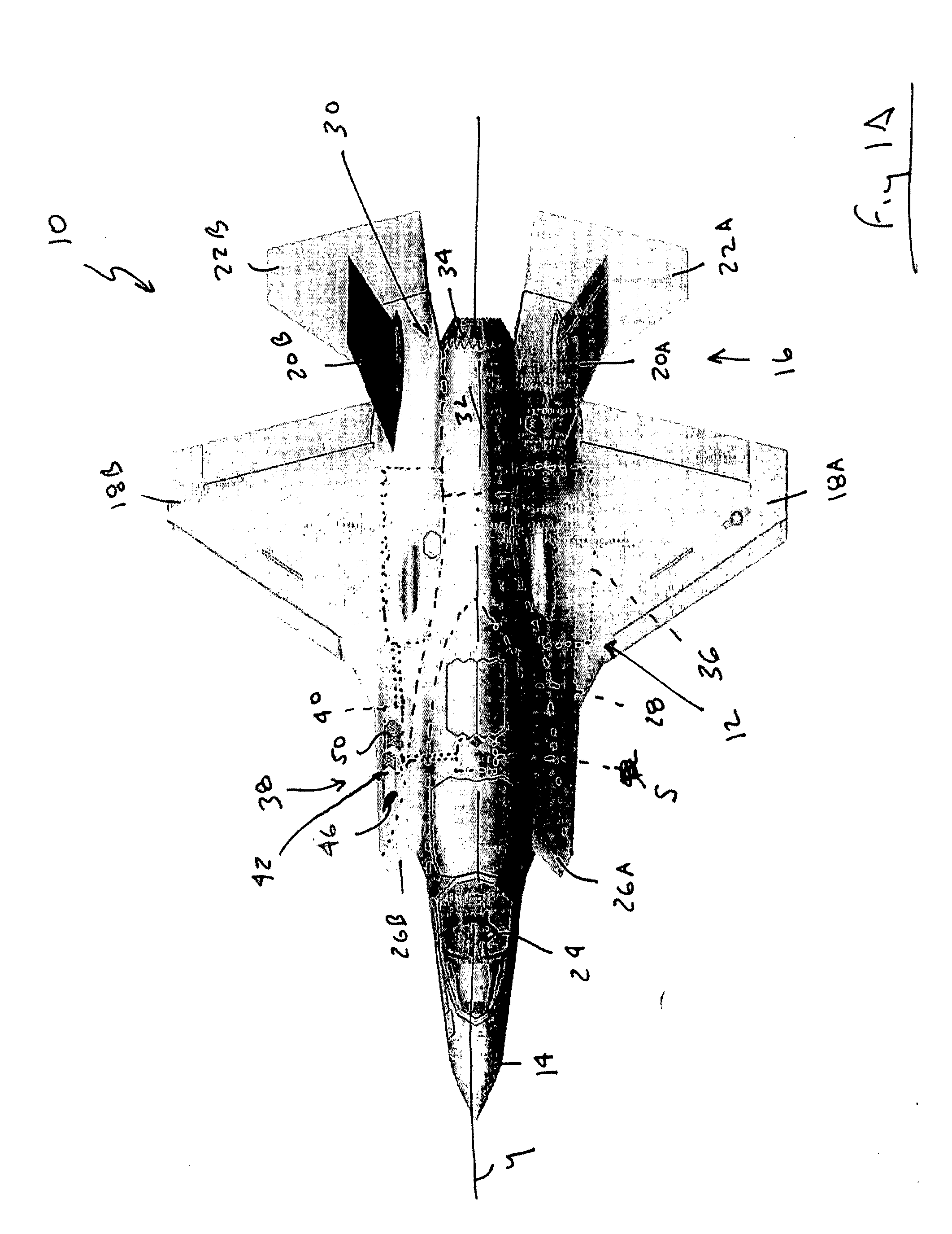
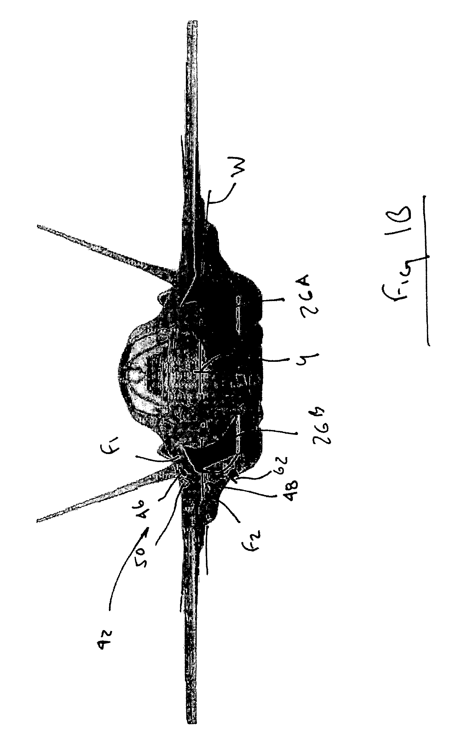
[0016]FIG. 1A illustrates an exemplary aircraft 10 which defines a longitudinal axis Y. The aircraft 10 includes an airframe 12 with a nose section 14, a tail section 16, wings 18A and 18B, vertical stabilizers 20A, 20B, and horizontal stabilizers 22A and 22B. Other features include a cockpit 24, engine inlets 26A and 26B which join to form an engine inlet duct 28. Although a particular aircraft configuration is illustrated in the disclosed embodiment, other aircraft types will also benefit from the present invention.

[0017]A propulsion system 30 generally includes a turbofan engine 32 in communication with duct 28. The engine 32 includes an exhaust nozzle section 34 generally between the horizontal stabilizers 22A, 22B. A fuel system 36 communicates with the propulsion system 30.

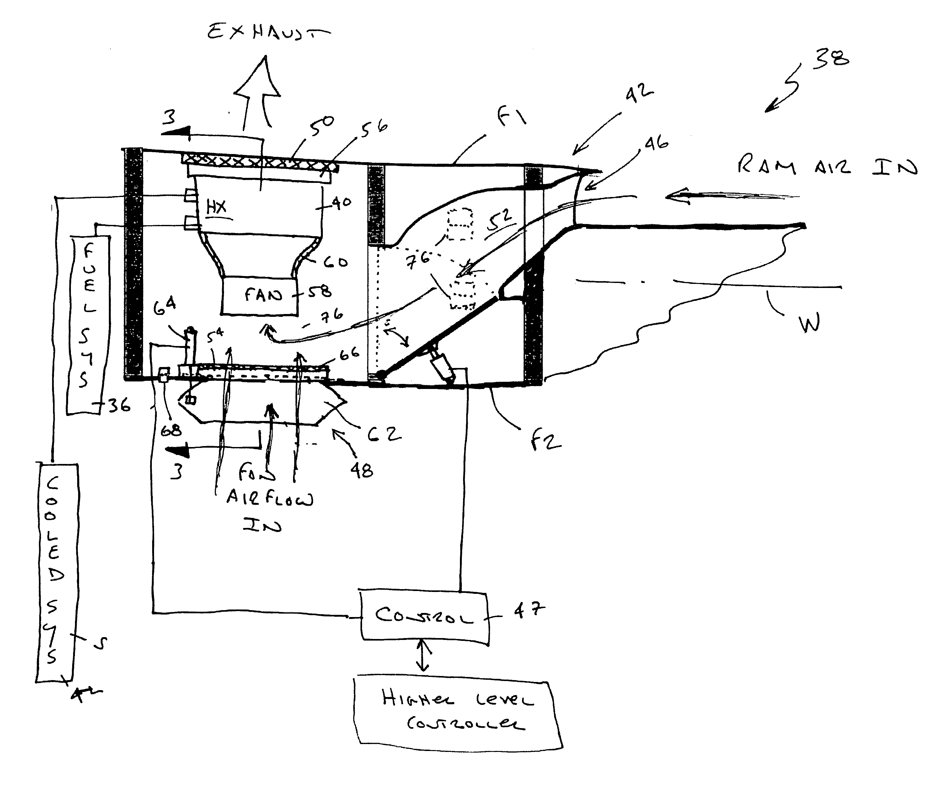
[0018]A thermal management system 38 includes a multitude of heat exchangers 40 (only one shown) in communication with the fuel system 36. The heat exchanger 40 facilitates the rejection of thermal loads fro...


PUM


Abstract

A thermal management system includes a cooling duct system that locates a ram air intake and an exhaust through a first aircraft surface above a second aircraft surface which locates a fan intake. During ground operations, an anti-re-ingestion door is open and a ram air door is closed such that the fan system may draw relatively cooler air from below the aircraft and exhaust the heated air above the aircraft to minimize re-ingestion of the heated exhaust. During flight operations, the anti-re-ingestion door is closed and the ram air door is open such that ram airflow communicates through the fan system prior to communication through the heat exchanger. Both the anti-re-ingestion door and the ram air door may also be operated in flight.

Description

BACKGROUND OF THE INVENTION[0001]The present invention relates to a thermal management system for an aircraft gas turbine engine, and more particularly to a heat exchanger cooling duct system that reduces system pressure drop and resists re-ingestion of heated airflow from the heat exchanger during aircraft ground operations.[0002]Aircraft thermal management systems are utilized to cool various components and systems including for example the engine oil system, avionics systems and mechanical components. Tactical aircraft in particular place a premium on space such that systems that require cooling airflow are often packaged within the airframe in a manner which complicates effective thermal management thereof. Such aircraft are required to operate in airport environments which further complicate effective thermal management such as high altitude and hot ambient temperature environments. Still other operational conditions such as where a multitude of aircraft are stacked up on taxiw...

Claims


Application Information

Patent Timeline
Patent Type & Authority Applications(United States)
IPC IPC(8): F02C1/00
CPCB64D33/02F02C7/055F02C7/042B64D2033/0273
Inventor SCHWARZ, FREDERICK M.
Owner RAYTHEON TECH CORP
Why Eureka
Try Eureka