Electrical Junction Box

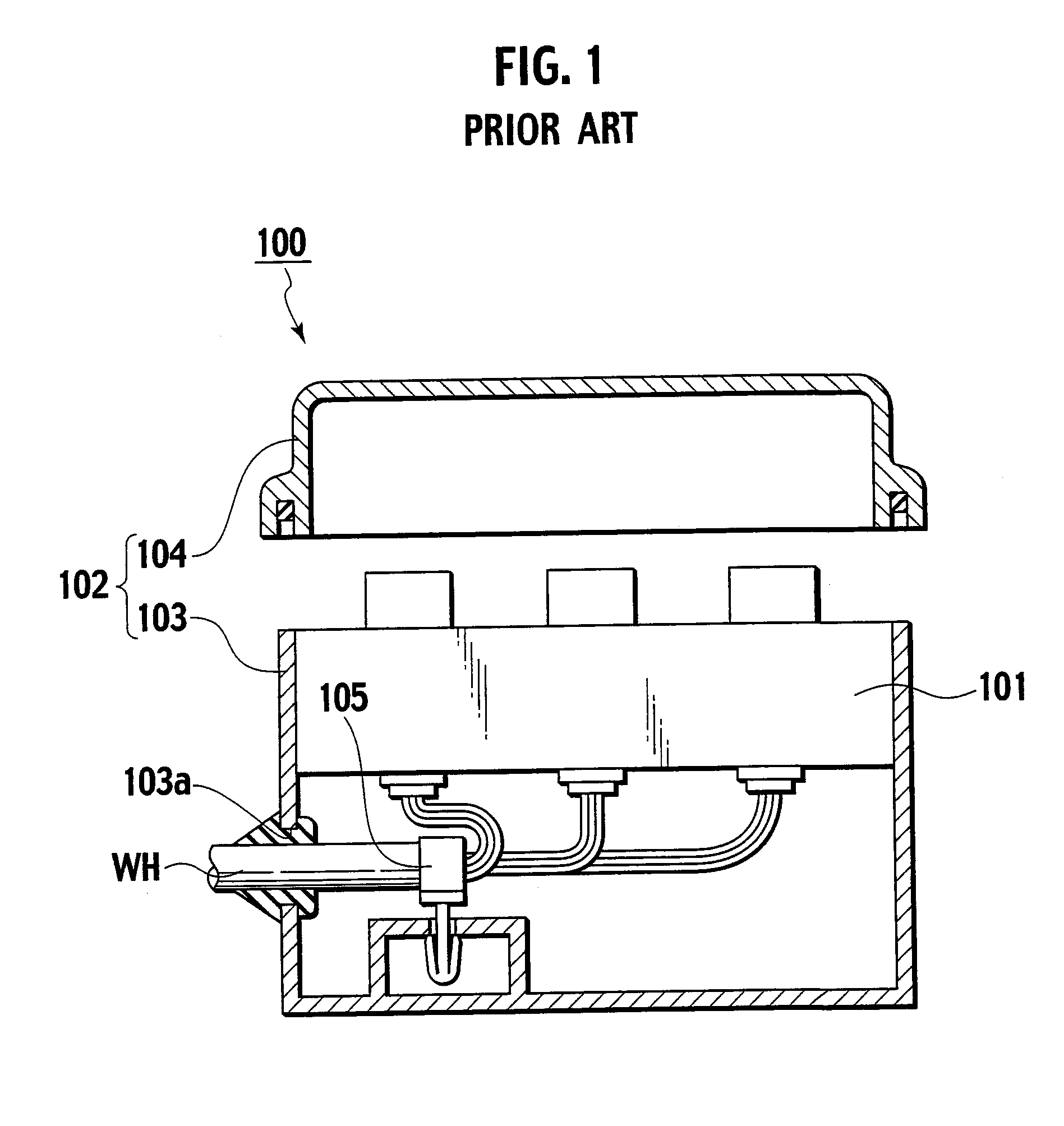
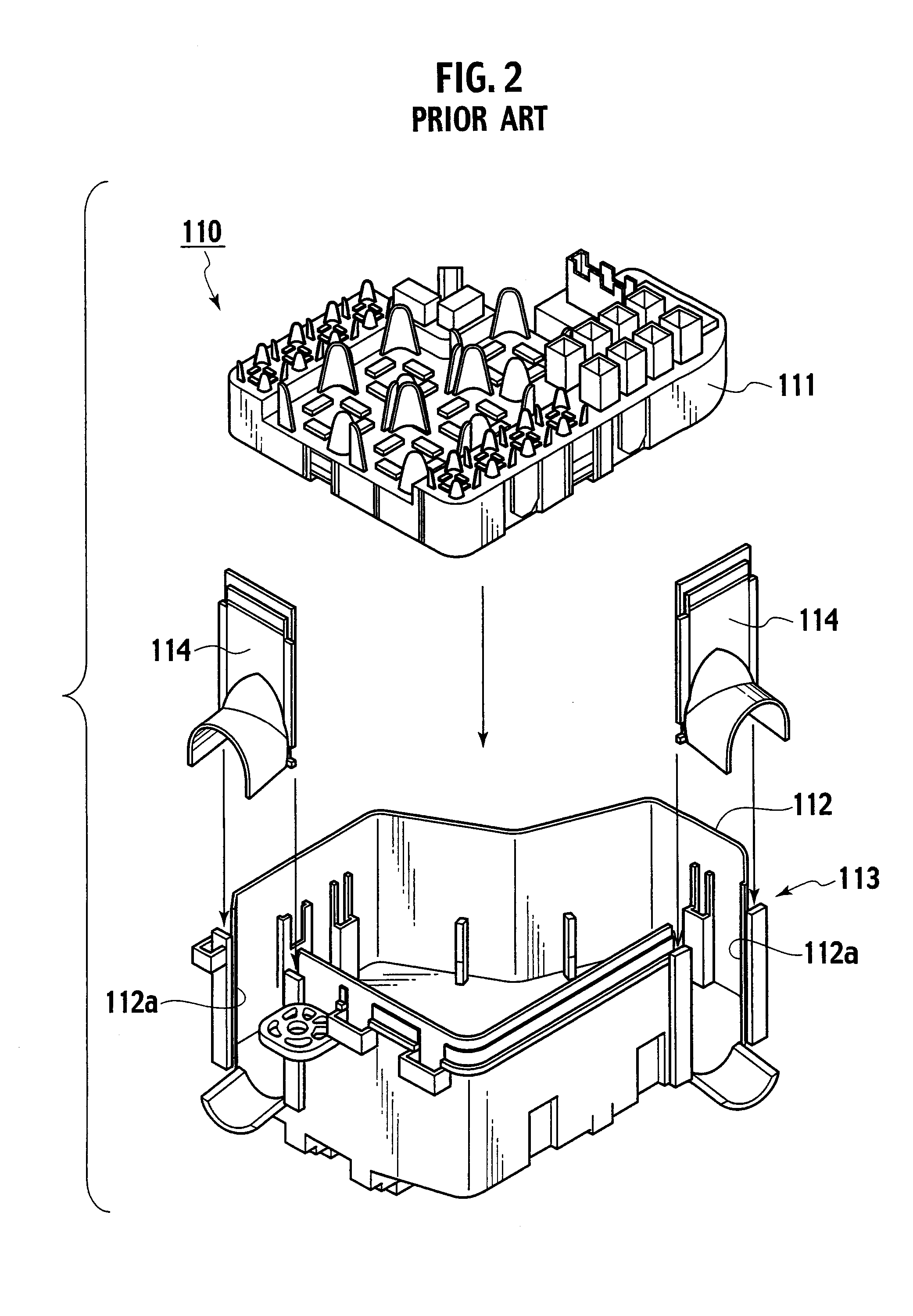
a junction box and electrical technology, applied in the direction of lighting conductor installation, coupling device connection, semiconductor/solid-state device details, etc., can solve the problems of poor assemblability of the electrical junction box, and complicated harness lead-out operation

Active Publication Date: 2008-03-06
YAZAKI CORP
View PDF3 Cites 19 Cited by
  • Summary
  • Abstract
  • Description
  • Claims
  • Application Information

AI Technical Summary

Benefits of technology

[0022] According to the configuration described above, in addition to the above effects, the harness lead-out direction guiding part can be easily formed.

Problems solved by technology

Thus, a harness lead-out operation becomes complicated.
As a result, there is a problem of poor assemblability of the electrical junction box 100.
Thus, as in the case of the electrical junction box 100 disclosed in Japanese Patent Application Laid-Open Publication No. 2001-112148, a harness lead-out operation becomes complicated.
As a result, there is a problem of poor assemblability of the electrical junction box 110.

Method used


Image

  • Electrical Junction Box
  • Electrical Junction Box
  • Electrical Junction Box

Examples


Embodiment Construction

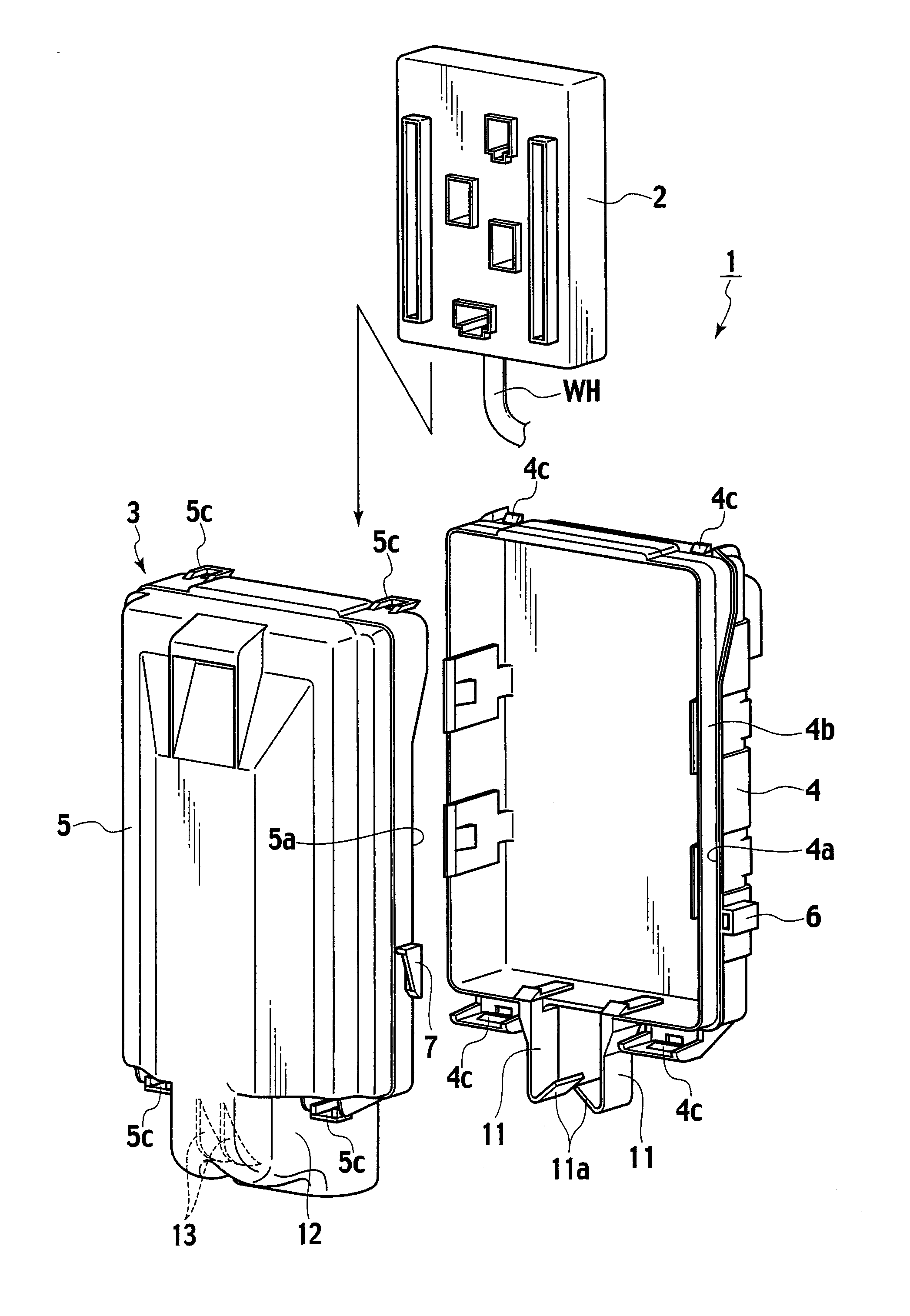
[0032] With reference to the drawings, an embodiment of the present invention will be described below. In the following description of the drawings, the same or similar parts will be denoted by the same or similar reference numerals. FIGS. 3 to 9 show one embodiment of the present invention. FIG. 3 is an exploded perspective view of an electrical junction box. FIG. 4 is a perspective view of the electrical junction box. FIG. 5 is a back view of the electrical junction box. FIG. 6 is a front view of a harness temporary holding part of an under case member. FIG. 7 is a view showing inside of a harness cover part of an upper case member. FIG. 8 is a back view showing a state where a wire harness is led out from a housing case. FIG. 9 is a cross-sectional view along the line IX-IX in FIG. 8.

[0033] As shown in FIGS. 3 to 5, an electrical junction box 1 includes an electrical junction box main body 2 and a housing case 3 which houses the electrical junction box main body 2 therein and co...


PUM


Abstract

In an electrical junction box, an electrical junction box main body is housed in a housing case consisting of an under case member and an upper case member, and a wire harness having its one end connected to the electrical junction box main body is led out to the outside of the housing case. The under case member has a pair of holding arms provided therein, which temporarily hold the wire harness to be led out roughly in a desired lead-out direction, the wire harness being led out from the under case member, in a state where the electrical junction box main body is temporarily housed in the under case member. The upper case member has guide ribs provided therein, which guide the wire harness in the desired lead-out direction, the wire harness being led out roughly in the desired lead-out direction by the pair of holding arms in the under case member, in an assembled state of the under case member and the upper case member.

Description

BACKGROUND OF THE INVENTION [0001] 1. Field of the Invention [0002] The present invention relates to an electrical junction box having an electrical junction box main body housed in a housing case, and more particularly relates to a wire harness lead-out structure for leading out a wire harness to outside of the housing case. [0003] 2. Description of the Related Art [0004] As related electrical junction boxes, there are ones disclosed in Japanese Patent Application Laid-Open Publication No. 2001-112148 and in Japanese Patent Application Laid-Open Publication No. 2000-166058. As shown in FIG. 1, an electrical junction box 100 disclosed in Japanese Patent Application Laid-Open Publication No. 2001-112148 includes an electrical junction box main body 101 and a housing case 102 which consists of an under case member 103 and an upper case member 104 for housing the electrical junction box main body 101 therein. A wire harness WH having its one end connected to the electrical junction box...

Claims


Application Information

Patent Timeline
Patent Type & Authority Applications(United States)
IPC IPC(8): H02G3/16
CPCB60R16/0239Y10S248/906
Inventor NAKAYAMA, MAKOTOHASHIMOTO, KATSUYAMIZUNO, HIROFUMI
Owner YAZAKI CORP
Why Eureka
Try Eureka