Acoustic/Pressure Wave-Driven Separation Device
- Summary
- Abstract
- Description
- Claims
- Application Information
AI Technical Summary
Problems solved by technology
Method used
Image
Examples
second embodiment
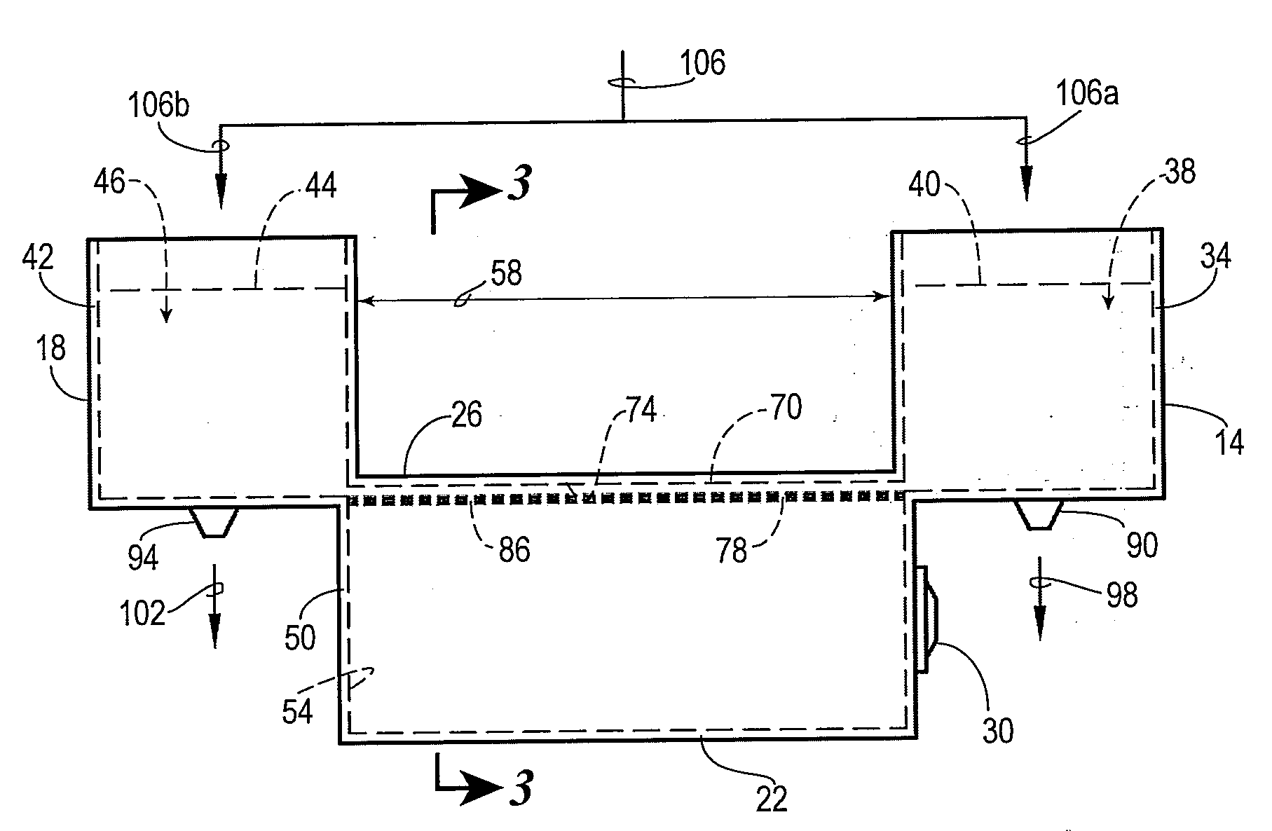
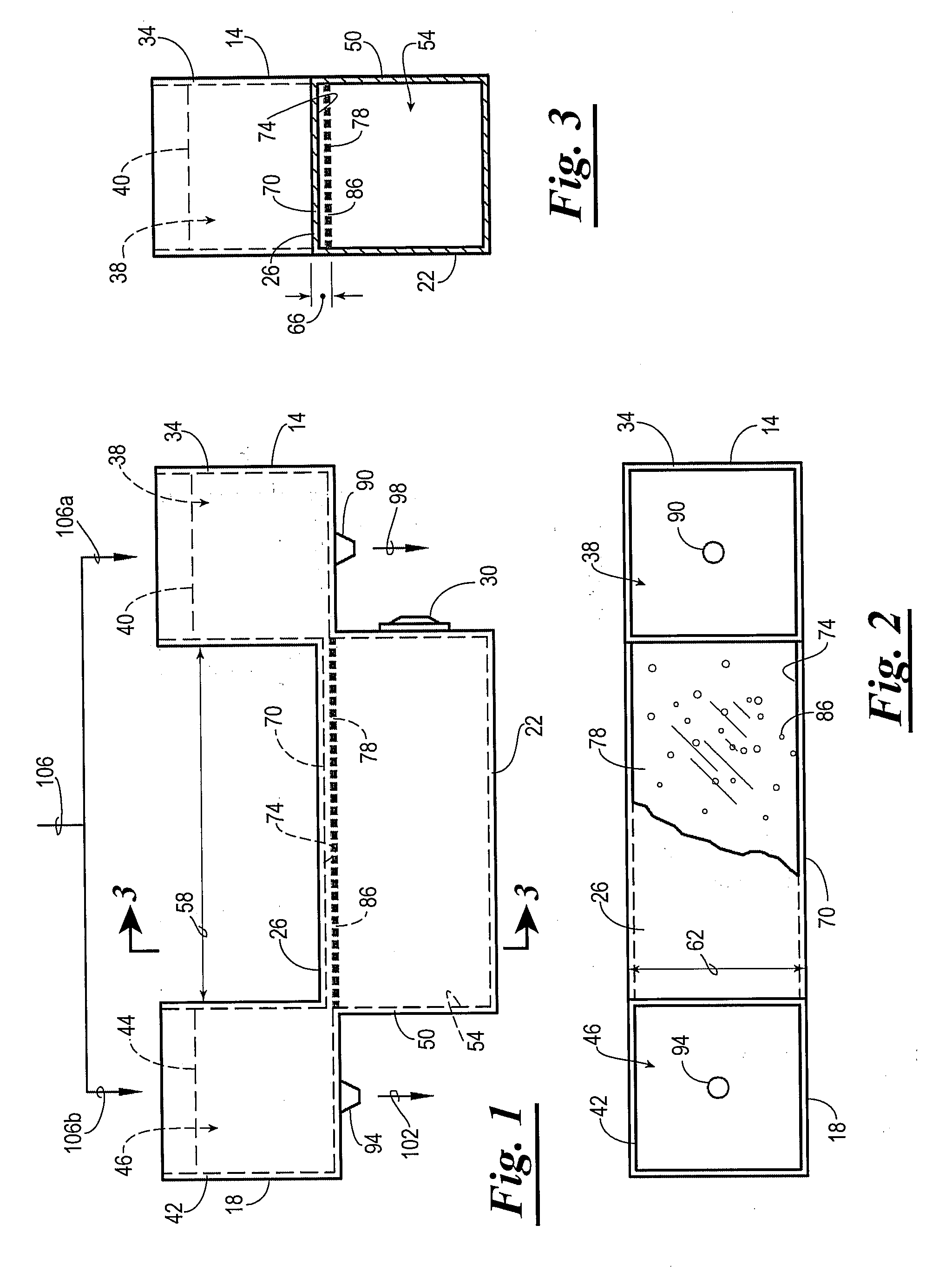
[0082] Referring again to the drawings, shown in FIG. 6 is a perspective-view diagram of an acoustically / pressure wave-driven separation device 10a as constructed in accordance with the present invention and referred to therein by the general reference numeral 10a. The device 10a is similar in many respects, in both form and function, to the device 10 of FIGS. 1-5G. Specifically, the device 10a is preferably provided with a lean reservoir 14a, a rich reservoir 18a, a pump reservoir 22a, a bridge structure 26a, and an acoustic / pressure wave source 30a. The lean and rich reservoirs 14a and 18a, respectively, are filled during operation with crude mixture streams 106a and 106b, respectively. Similarly, the lean and rich reservoirs 14a and 14b, respectively, are drained by lean and rich product streams 98a and 102a, respectively, via product outlets 90a and 94a, respectively.
[0083] The primary difference between the device 10a and the device 10 (FIGS. 1-3), is that the bridge structure ...
third embodiment
[0085] Referring now to FIG. 7, shown therein is a side-view diagram of an acoustic / pressure wave-driven separation device constructed in accordance with the present invention and referenced therein by general reference numeral 10b. The device 10b is adapted with three concentration reservoirs 250a, 250b, and 250c, such that the device 10b is capable of separating a crude mixture into three components and / or component mixtures or sub-mixtures. With the exception of several changes in form and the addition of an additional separation function, the device 10b is similar in many respects, in both form and function, to the device 10 of FIGS. 1-3 and the device 10a of FIG. 6. The device 10, 10a and 10b can have one or more pressure wave source(s) and one or more pump reservoir.
[0086] For example, the device 10b is provided with a plurality of concentration reservoirs, e.g. 250a, 250b, and 250c (and optionally more than three), a pump reservoir 22b, a bridge structure 26b, and an acoustic...
fourth embodiment
[0091] Referring now, to FIG. 8, a side view diagram of an acoustic / pressure wave-driven device, for separating a mixture into five components, constructed in accordance with the present invention and designated by the general reference numeral 10c. Similar to the device 10b of FIG. 7, the device 10c is provided with a plurality of concentration tanks 260a, 260b, 260c, 260d, and 260e, each having an inner space 264a, 264b, 264c, 264d, and 264e, respectively. The device 10c also preferably comprises a bridge structure 26c defining a gradient channel 74c extending across and in fluid communication with each of the spaces 264a, 264b, 264c, 264d, 264e so as to permit the various target components A, B, C, D, E to maintain respective concentration gradients within the gradient channel 74c. Additionally, the device 10c is provided with at least one acoustic / pressure wave source 30c similar to the other acoustic / pressure wave sources 30-30b described elsewhere herein.
[0092] The primary dif...
PUM
 Abstract
Description
Claims
Application Information
 - R&D
- Intellectual Property
- Life Sciences
- Materials
- Tech Scout
- Unparalleled Data Quality
- Higher Quality Content
- 60% Fewer Hallucinations
Browse by: Latest US Patents, China's latest patents, Technical Efficacy Thesaurus, Application Domain, Technology Topic, Popular Technical Reports.
© 2025 PatSnap. All rights reserved.Legal|Privacy policy|Modern Slavery Act Transparency Statement|Sitemap|About US| Contact US: help@patsnap.com


