Steering damper mounting structure for vehicle

Inactive Publication Date: 2008-03-06
HONDA MOTOR CO LTD
View PDF11 Cites 8 Cited by
  • Summary
  • Abstract
  • Description
  • Claims
  • Application Information

AI Technical Summary

Benefits of technology

[0023]In accordance with the first aspect of the present invention, the portion on the side of the head pipe supporting the steering damper is disposed on the side of the center of pivotal motion of the front fork relative to the portion on the side of the fork bridge supporting the steering damper. As compared with a case, in which the steering damper is disposed such that the axis thereof extends in parallel with the axis of the head pipe, protrusion of the entire steering damper forward of the vehicle can be suppressed and the space required for the steering damper to rotate becomes smaller. If, for example, a cover member covering the steering damper is disposed around the steering damper, the cover member is not largely away from the head pipe, thus promoting reduction in size of the front portion of the vehicle. Additionally, the smaller stroke of the steering damper contributes to a smaller steering damper.
[0024]In accordance with the second aspect of the present invention, the mounting surface disposed on the fork bridge for mounting the steering damper on the fork bridge is formed to be in parallel with the axis of the steering damper when the handlebar steering angle is zero. Accordingly, the pivotal motion range of the steering damper can be made even greater. The aspect of the present invention can therefore respond to a vehicle involving a large steering angle.
[0025]In accordance with the third aspect of the present invention, the steering damper includes the main body having a cylinder, the piston movably inserted in the cylinder, and the rod disposed on the piston. Further, the main body is supported on the head pipe and the rod is supported on the fork bridge. Specifically, the rod, which is lighter in weight than the main body accommodating the piston, is supported on the fork bridge. This arrangement helps make small the inertia force generated during rotation of the fork bridge, contributing to an improved steering feel felt via the handlebar.
[0026]In accordance with the fourth aspect of the present invention, the fork bridge includes the protrusion that contacts the main body to thereby prevent erroneous installation, in which the steering damper is installed invertedly between the head pipe and the fork bridge. The protrusion comes in contact with the main body if the main body of the steering damper is mounted to the fork bridge or the rod of the steering damper is mounted to the head pipe. Erroneous installation can thus be prevented with such a simple structure.

Problems solved by technology

This not only suppresses protrusion of the entire steering damper forward of the vehicle, but also makes small an amount of stroke of the steering damper.

Method used


Image

  • Steering damper mounting structure for vehicle
  • Steering damper mounting structure for vehicle
  • Steering damper mounting structure for vehicle

Examples


Embodiment Construction

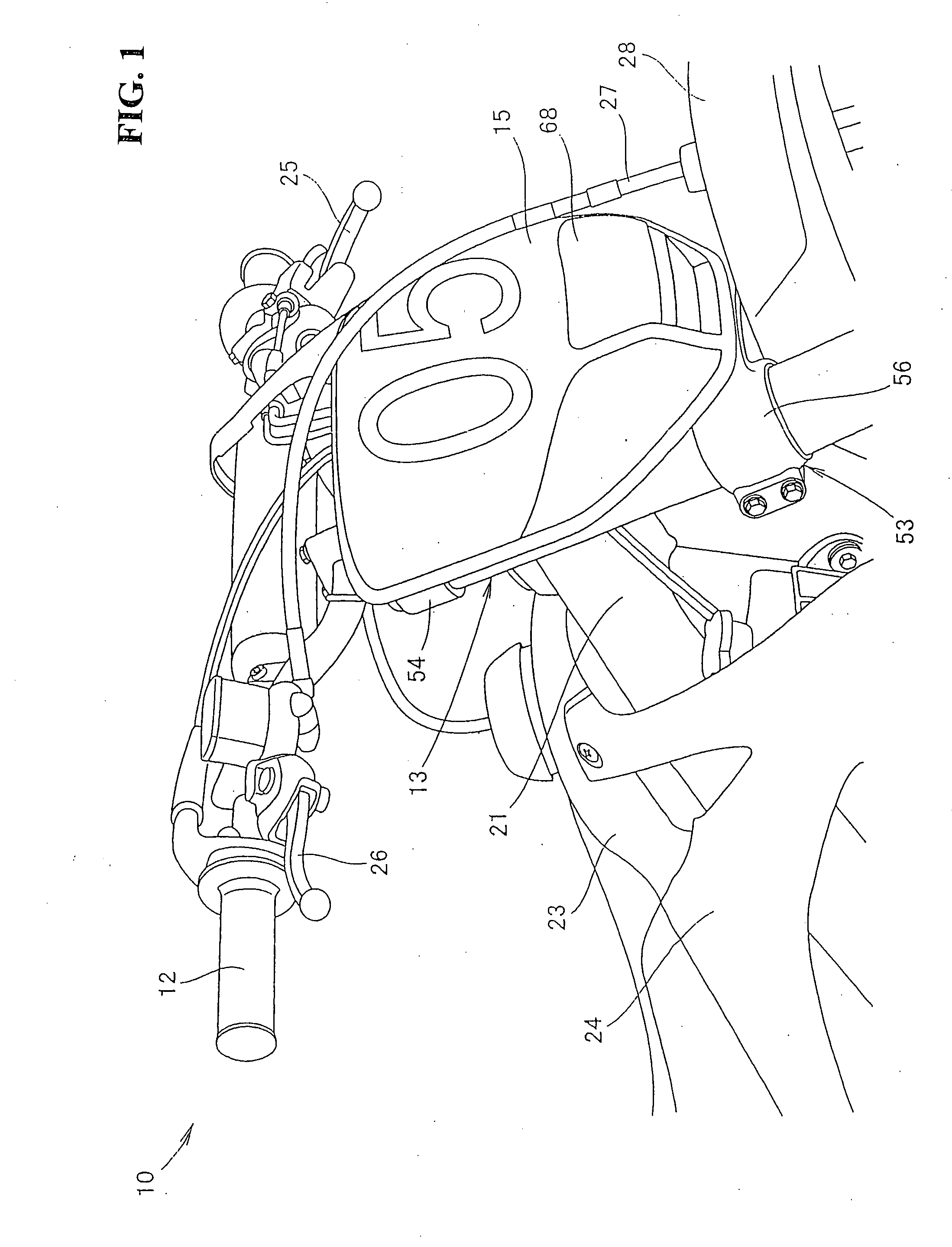
[0039]FIG. 1 is a perspective view showing a front portion of a vehicle having a steering damper according to an embodiment of the present invention. A vehicle 10 is an off-road motorcycle. A handlebar 12 is fitted to an upper end of a front fork 13 that supports a front wheel at a lower end thereof. A steering damper (not shown) to be described in detail later is mounted on an upper portion of the front fork 13. A number plate 15 marked with a competition identification number is disposed so as to cover a forward area of the steering damper.

[0040]Referring to FIG. 1, reference numeral 21 represents a vehicle body frame serving as a framework for the vehicle 10. The front fork 13 is steerably mounted to a head pipe (not shown) disposed at a front end of the vehicle body frame 21.

[0041]FIG. 1 also shows a fuel tank 23 mounted at an upper portion of the vehicle body frame 21, a cowl 24 that covers a front side portion of a vehicle body, a clutch lever 25 and a front wheel brake lever ...


PUM


Abstract

A steering damper mounting structure of a vehicle includes a head pipe, a front fork, a fork bridge, and a steering damper. The front fork, which suspends a front wheel, is steerably disposed on the head pipe. The fork bridge connects left and right members of the front fork. The steering damper is mounted on the fork bridge and the head pipe. The steering damper dampens a steering directional movement transmitted from a road surface to a handlebar via the front wheel and the front fork. A lower mounting portion on a side of the head pipe is disposed on a side of an axis as a center of pivotal motion of the front fork relative to the fork bridge, more specifically, an upper mounting portion on a side of the top bridge. The resulting configuration reduces the size of a front portion of a vehicle and a steering damper.

Description

CROSS-REFERENCE TO RELATED APPLICATION[0001]The present application claims priority under 35 U.S.C. §119 to Japanese Patent Application No. 2006-233966, filed Aug. 30, 2006, the entire contents of which are hereby incorporated by reference.BACKGROUND OF THE INVENTION[0002]1. Field of the Invention[0003]The present invention relates to a vehicular steering damper mounting structure that dampens a steering directional movement transmitted from a road surface to a handlebar via a front wheel and a front fork.[0004]2. Description of Background Art[0005]A known vehicular steering damper mounting structure includes a steering damper disposed between a head pipe and a fork bridge on a side of a front fork and to extend in parallel with the head pipe (see, for example, Japanese Patent Laid-open No. 2005-96735).[0006]The arrangement disclosed in FIGS. 1 and 2 of Japanese Patent Laid-open No. 2005-96735 will be described below.[0007]A vehicle includes a head pipe 6h disposed at a front end of...

Claims


Application Information

Patent Timeline
IPC IPC(8): B62K21/08
CPCB62K21/08
Inventor MORI, YOTAROFUSE, TOMOHIROUCHIYAMA, MIKIO
Owner HONDA MOTOR CO LTD
Why Eureka
Try Eureka