
Liftable cover

a technology of lifting cover and pivotal hole, which is applied in the field of covers, can solve the problems of plastic members being damaged by metallic springs, the clearance between the pivotal shaft and the pivotal hole may become larger, and the pivotal shaft cannot always penetrate into the pivotal hole very smoothly, so as to achieve the effect of easy replacemen

Inactive Publication Date: 2008-03-06
CHEMTRON RES
View PDF13 Cites 2 Cited by
  • Summary
  • Abstract
  • Description
  • Claims
  • Application Information

AI Technical Summary

Benefits of technology

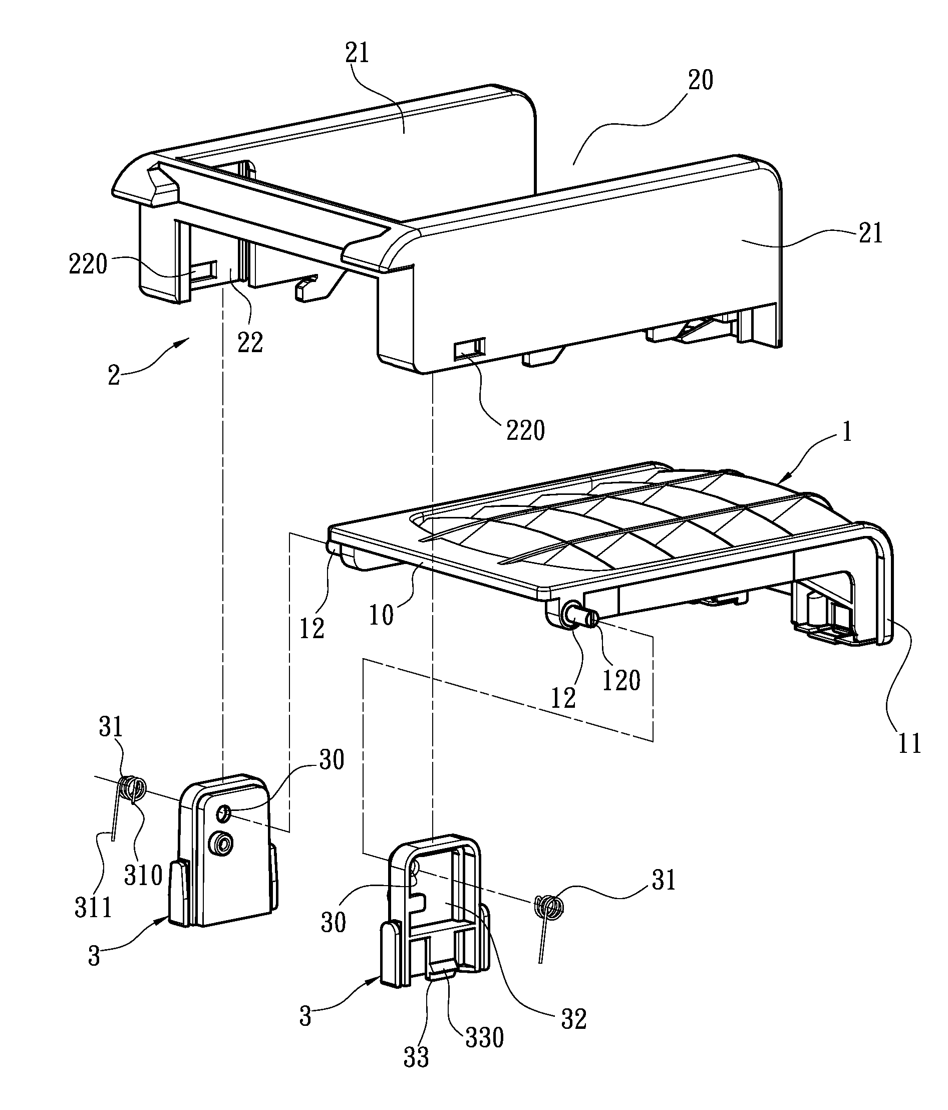
[0010]The present invention is to provide a structure of a liftable cover, in which a covering seat is provided to allow a cover to be pivoted thereon. The pivotally connecting positions between the cover and the covering seat are provided with a pivotal sliding block respectively. Via the pivotal sliding blocks, the cover and the covering seat are pivotally connected with each other in an indirect manner. As a result, when the pivotal holes on the pivotal sliding blocks are enlarged due to the wear and the pivotally connecting function is lost, new pivotal sliding blocks can be replaced easily, thereby maintaining the lifting and covering functions of the liftable cover in a low-cost manner.
[0011]The present invention is to provide a structure of a liftable cover. Via the above pivotal sliding blocks, elements such as torsion springs can be attached thereon easily. Further, since the pivotal sliding blocks can be replaced, the problem of the damage of resilient elements caused by the accumulated force can be also solved.
[0012]The present invention is to provide a structure of a liftable cover. After the pivotal sliding blocks are pivoted to pivotally connecting positions of the cover, they slide on the covering seat. Via such a two-stage assembly, a fast and convenient way of pivotally connecting can be achieved.

Problems solved by technology

Therefore, the pivotal shaft cannot always penetrate into the pivotal holes very smoothly, and thus it is necessary to incline the pivotal shaft to facilitate the penetrating action.
Especially, since the springs are generally made of metallic materials while the surrounding members are made of plastics, the plastic members will be damaged by the metallic springs.
3. Since the pivotal shaft is pivoted into the pivotal holes directly and the pivotal holes are provided on the connecting portion, after a long-term use, the pivotal shaft and the pivotal holes will be worn, so that the clearance between the pivotal shaft and the pivotal holes may become larger and thus the pivotal connection may get loose.
To a serious extent, the pivotal connection may break down.

Method used


Image

  • Liftable cover
  • Liftable cover
  • Liftable cover

Examples


Embodiment Construction

[0022]In order to make the Examiner to better understand the characteristics and technical contents of the present invention, a detailed description will be made with reference to the accompanying drawings. However, it should be understood that the drawings are illustrative only but not to limit the scope of the present invention.

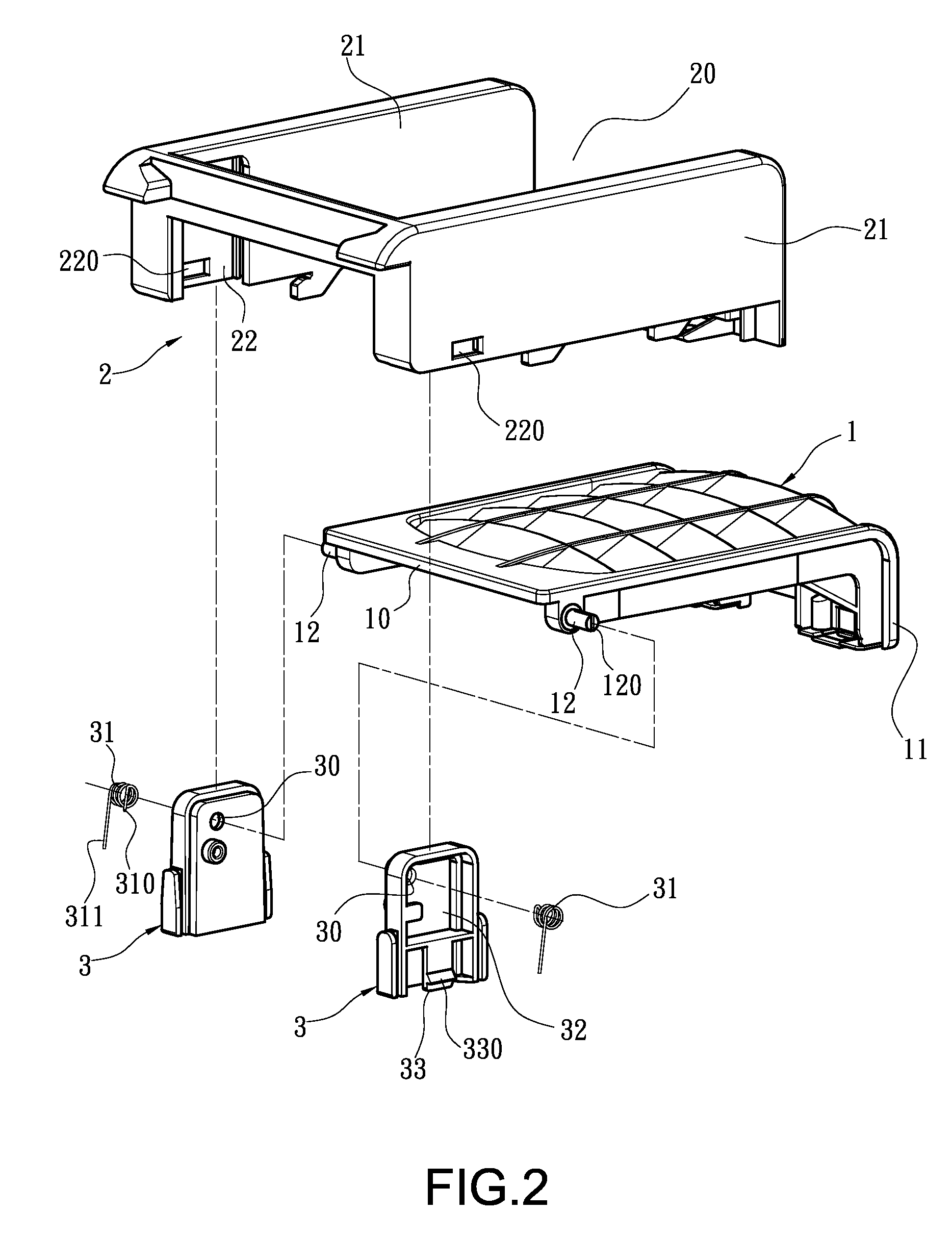
[0023]FIG. 2 is an exploded perspective view of the present invention. FIG. 3 is an assembled perspective view showing that the present invention is lifted, and FIG. 4 is an assembled perspective view showing that the present invention is covered. The present invention provides a structure of a liftable cover, which includes a cover 1 and a covering seat 2.

[0024]The cover 1 has a pivoting end 10. The pivoting end 10 is usually located at one end of the cover 1, and can be also located in the middle section of the cover 1. The other end of the cover 1 has a cover-lifting end 11. With the pivoting end 10 of the cover 1 being pivotally connected on the coverin...


PUM


Abstract

A structure of a liftable cover includes a cover having a pivoting end and a covering seat that allows the cover to be disposed thereon. The covering seat is formed thereon with a notch. Both sides of the notch are formed with a sidewall for the covering seat respectively. The notch is hollowed in the vertical direction. Both ends of the pivoting end of the cover are pivotally provided with a pivotal sliding block. The sidewalls on both sides of the covering seat are provided with a sliding trough to correspond to the pivotal sliding block respectively. The two pivotal sliding blocks slide into the two sliding troughs and are connected thereto respectively. Via the indirect pivotal connection of the two pivotal sliding blocks, components can be replaced and assembled in a rapid and convenient manner.

Description

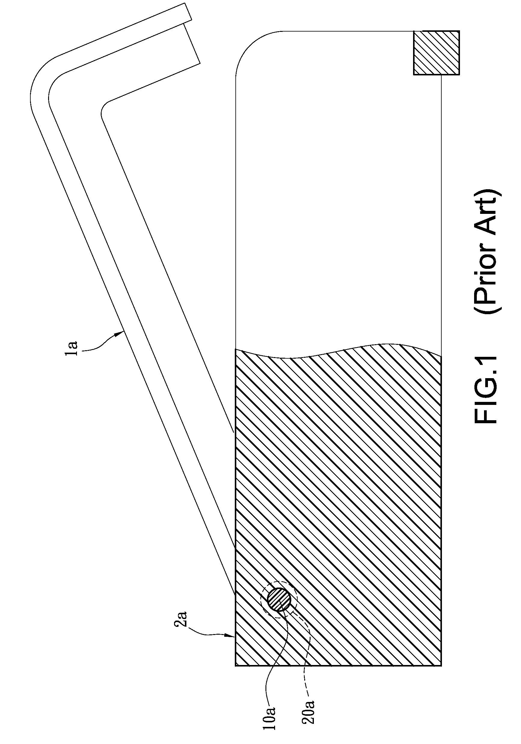
BACKGROUND OF THE INVENTION[0001]1. Field of the Invention[0002]The present invention relates to a cover, and in particular to a liftable cover that can be lifted upwardly and cover downwardly, and the structure of a pivotally connecting portion thereof is improved.[0003]2. Description of Prior Art[0004]As shown in FIG. 1, a common cover 1a that can be lifted is formed by means of directly pivoting a pivotal means such as a pivotal shaft 10a to a connecting portion 2a. For example, both sides of one end of the cover 1a are provided with the pivotal shaft 10a, and the connecting portion 2a is provided with pivotal holes 20a that allow the pivotal shaft to be pivoted thereto. When the pivotal shaft 10a penetrates into the pivotal holes 20a, the cover 1a can be lifted upwardly or cover downwardly at the connecting portion 1a. [0005]However, with regard to the assembly process or the capability of attaching functional elements, the above-mentioned structure in which the cover is directl...

Claims


Application Information

Patent Timeline
Patent Type & Authority Applications(United States)
IPC IPC(8): A47C3/00
CPCH05K5/03
Inventor LING, MIAO-HUNG
Owner CHEMTRON RES
Learn More