

Permanent magnet and permanent magnet rotating machine
Active Publication Date: 2008-03-06
SHIN ETSU CHEM IND CO LTD
View PDF17 Cites 14 Cited by
- Summary
- Abstract
- Description
- Claims
- Application Information
AI Technical Summary
Benefits of technology
[0016] The D-shaped permanent magnet of the invention is unsusceptible to demagnetization, and can reduce cogging torque and increase drive torque. It is useful in the
Problems solved by technology
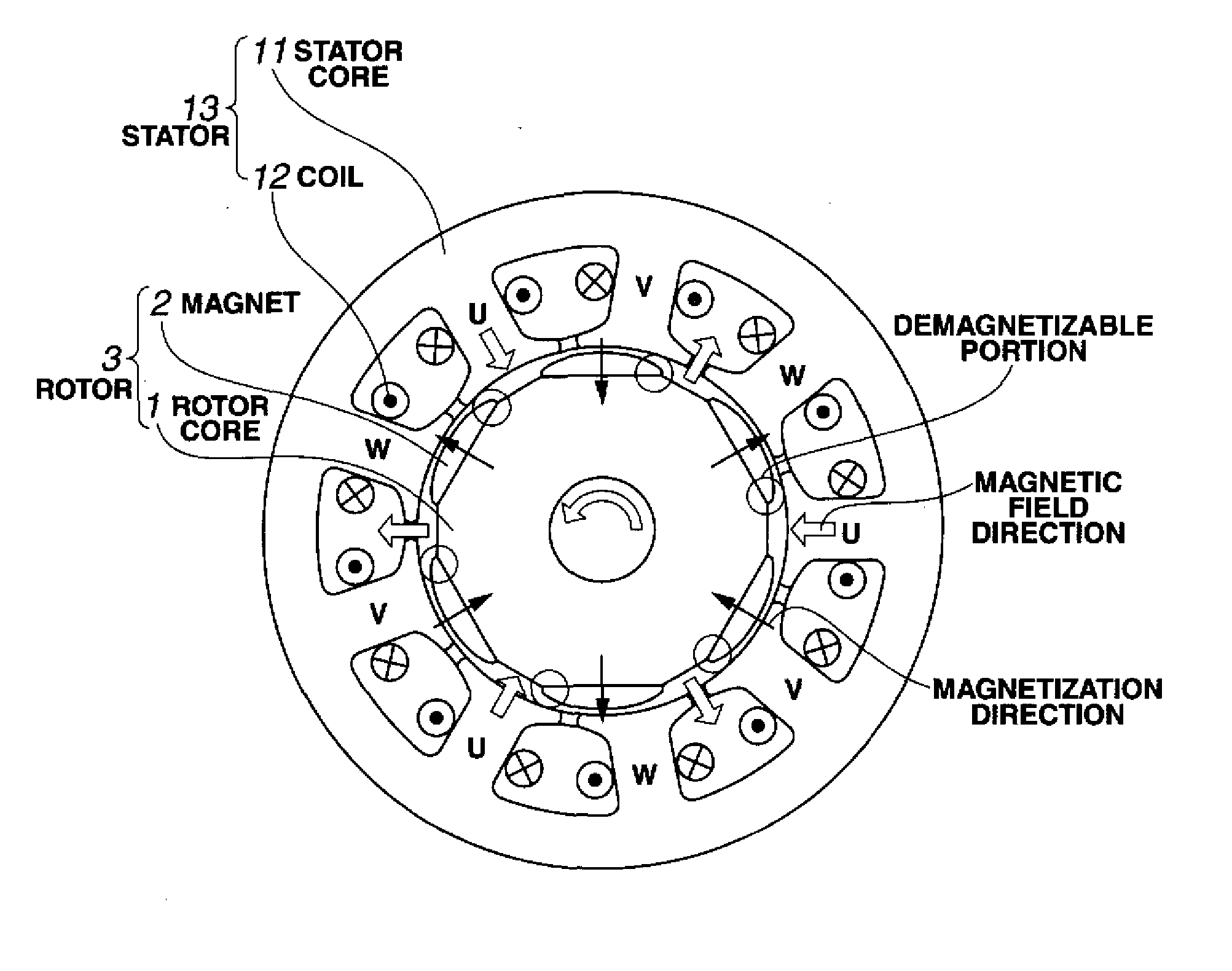
Accordingly, it is undesired that when the permanent magnets rotate, the alignment of stator slots and the permanent magnets causes cogging torque to develop due to variations of the magnetic flux distribution across the gap (i.e., torque without current flowing across the coil) or torque ripple
Method used
View moreImage
Smart ImageViewing Examples

Examples
 PUM
 Abstract
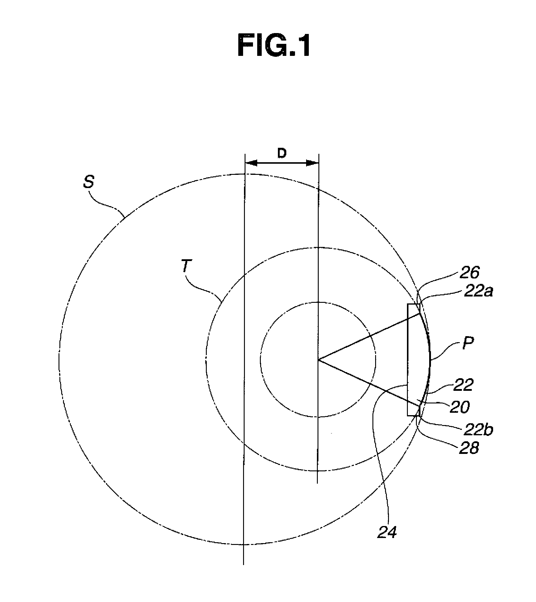
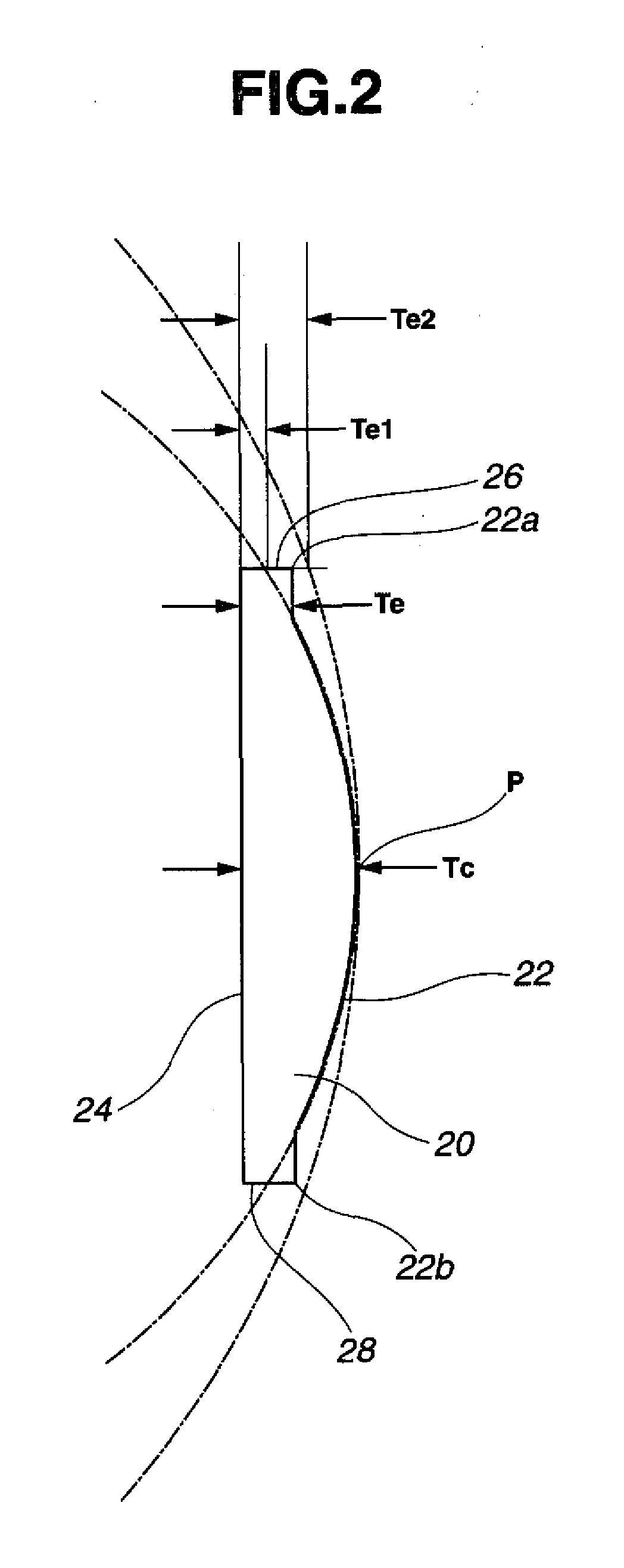
A permanent magnet has a D-shaped cross section including an arcuate top surface (22), a flat bottom surface (24), and side surfaces (26, 28). Provided that a plurality of permanent magnets are circumferentially arranged so that a great circle (S) circumscribes the apexes (P) on the arcuate top surfaces (22), the top surface (22) includes a central region which delineates an arc of a small circle (T) off-centered from the great circle, and end regions (22a, 22b) which are positioned outside the small circle (T) and inside the great circle (S).
Description
CROSS-REFERENCE TO RELATED APPLICATION [0001] This non-provisional application claims priority under 35 U.S.C. §119(a) on Patent Application No. 2006-233450 filed in Japan on Aug. 30, 2006, the entire contents of which are hereby incorporated by reference. TECHNICAL FIELD [0002] This invention relates to a D-shaped permanent magnet, and a synchronous permanent magnet rotating machine comprising the same, such as a servo motor, DC brushless motor or power generator. BACKGROUND ART [0003] Due to high efficiency and precise control abilities, permanent magnet (PM) rotating machines are commonly used as control motors, typically servo motors. In AC servo motors, for example, a permanent magnet rotating machine with a radial air gap as illustrated in FIG. 7 is used. This PM rotating machine comprises a rotor 3 including a rotor core 1 and a plurality of D-shaped permanent magnet segments 2 attached to the surface of the core, and a stator 13 surrounding the rotor 3 to define a gap thereb...
Claims
Login to View More Application Information
Patent Timeline
 IPC IPC(8): H01F7/02H02K1/27
CPCH02K1/278H02K1/2781H02K1/27H01F7/02
InventorMIYATA, KOJI
OwnerSHIN ETSU CHEM IND CO LTD