Entry control system and entry control method

a technology of entry control system and communication channel, which is applied in the direction of program control, instruments, anti-theft devices, etc., can solve the problems of difficult restriction of transmission range, risk of interception or obstruction,

Inactive Publication Date: 2008-03-06
KK TOSHIBA
View PDF15 Cites 133 Cited by
  • Summary
  • Abstract
  • Description
  • Claims
  • Application Information

AI Technical Summary

Benefits of technology

[0019]The entry control system as well as the entry control method according to the present invention allows f

Problems solved by technology

However, in application of the patent document 1 and the patent document 2, it is necessary for the user to have actions to make a card reader read a card, and wait in front of a door after an ID code has been read by the card reader, till an unlock following authentication, as a problem.
Further, for techniques of the patent document 3 employing wireless communications using an electric wave that can be transmitted e

Method used


Image

  • Entry control system and entry control method
  • Entry control system and entry control method
  • Entry control system and entry control method

Examples


first embodiment

Configuration of Entry Control System According to the First Embodiment

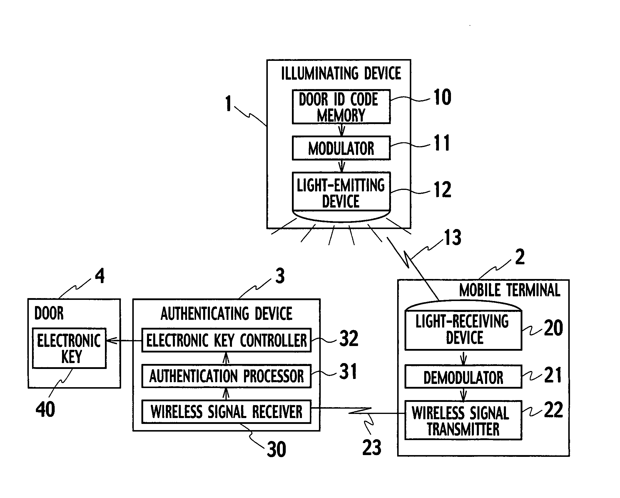
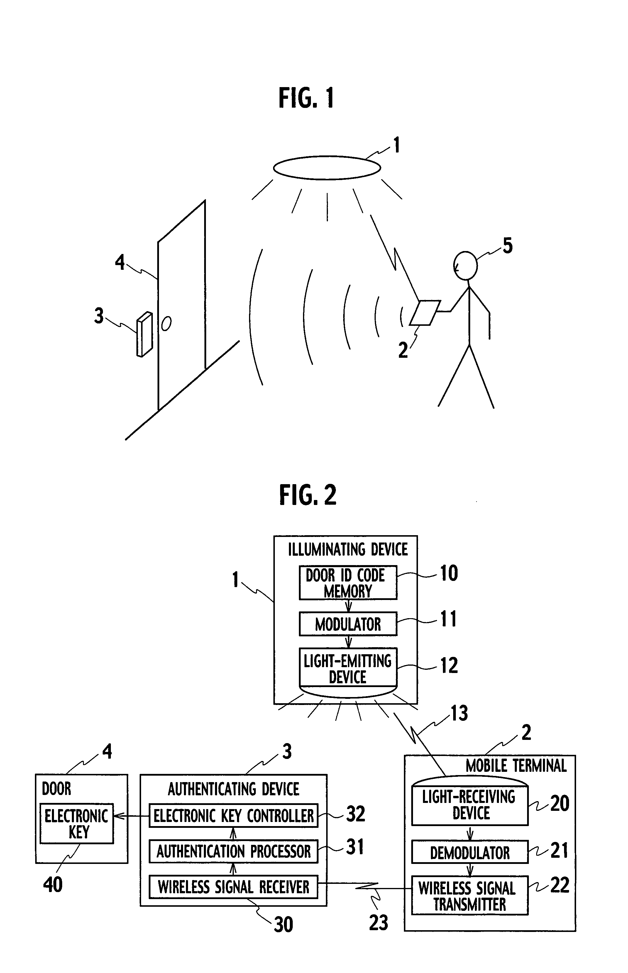
[0031]As shown in FIG. 1 and FIG. 2, the entry control system according to the present embodiment includes an illuminating device 1, a mobile terminal 2 portable by the user 5, an authentication device 3, and a door 4 for entry into a facility controlled of entry.

[0032]The illuminating device 1 has a door ID code memory 10, a modulator 11, and a light-emitting device 12.

[0033]The door ID code memory 10 stores therein a door ID code assigned to the door 4 as a unique ID code for unlocking the door 4.

[0034]The modulator 11 generates a light modulation signal by using the door ID code stored in the door ID code memory 10.

[0035]The light-emitting device 12 is made up by a visible-light emitting element (e.g. LED: light emitting diode) configured to be switched ON / OFF for emission of a modulated visible light signal 13 that is modulated by the light modulation signal generated by the modulator 11 into an illumination ...

second embodiment

Configuration of Entry Control System According to the Second Embodiment

[0055]As shown in FIG. 4, the entry control system according to the present embodiment includes an illuminating device 1, a mobile terminal 2 portable by the user 5, an authentication device 3, and a door 4 for entry into a facility.

[0056]The entry control system according to the present embodiment is identical to the first embodiment, except for the mobile terminal 2 having a terminal ID code memory 24, and redundant description is eliminated.

[0057]The terminal ID code memory 24 stores therein a terminal ID code assigned as unique information to the mobile terminal 2.

[0058]The mobile terminal 2 has a wireless signal transmitter 22, which acquires the terminal ID code from the terminal ID code memory 24, as well as a door ID code demodulated by a demodulator 21, and transmits them to the authentication device 3, using wireless communication 23.

[0059]The authentication device 3 has a wireless signal receiver 30, ...

third embodiment

Configuration of Entry Control System According to the Third Embodiment

[0067]As shown in FIG. 6, the entry control system according to the present embodiment includes an illuminating device 1, a mobile terminal 2, an authentication device 3, and a door 4 for entry into a facility.

[0068]The entry control system according to the present embodiment is identical to the first embodiment, except for the mobile terminal 2 having an input device 25 and a user ID code memory 26, and redundant description is eliminated.

[0069]The input device 25 is configured for operation by the user 5 to input a user ID code (e.g. PIN: personal identification number) for user identification.

[0070]The user ID code memory 26 stores therein the user ID code input by the input device 25.

[0071](Actions of Entry Control System According to the Third Embodiment)

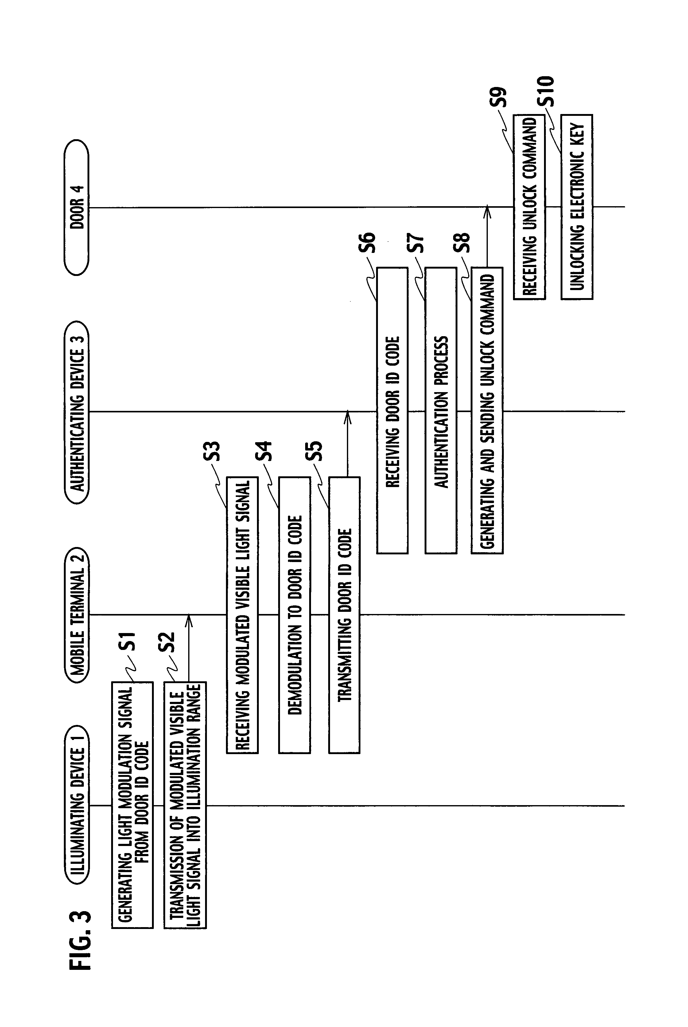
[0072]In FIG. 7, steps S31 to S34 are identical to the steps S1 to S4 in FIG. 3 of the first embodiment, and redundant description is eliminated.

[0073]At th...


PUM


Abstract

To provide an entry control system as well as an entry control method allowing for an easy entry of user, permitting a restriction to persons who have a legitimate right to enter a facility, an illuminating device (1) emits a modulated visible light signal 13 modulated by use of a door ID code into a preset illumination range, the modulated visible light signal 13 from the illuminating device (1) is received by a mobile terminal (2) portable by the user, where it is demodulated for wireless signal transmission, and the door ID code transmitted from the mobile terminal (2) is received by an authentication device (3), which judges whether or not the door ID code is legitimate, and generates an unlock command when the door ID code is judged to be legitimate, and a door (4) for a facility controlled of entry receives the unlock command from the authentication device (3), whereby it is unlocked.

Description

CROSS REFERENCE TO RELATED APPLICATION[0001]The present application claims the benefit of priority under 35 U.S.C. § 119 to Japanese Patent Application No. 2006-232407, filed on Aug. 29, 2006, the entire contents of which are incorporated herein by reference.BACKGROUND OF THE INVENTION[0002]1. Field of Art[0003]The present invention relates to an entry control system and an entry control method using visible-light communications for entry control of a facility.[0004]2. Description of Relevant Art[0005]As an entry control system for a facility, such as a building or condominium, of which the entry is limited to specific persons, there is a conventional system employing a card key in which an ID code is stored.[0006]This entry control system includes a card reader for reading an ID code stored in a key, such as a contact card using a magnetic effect or a non-contact card using an RFID (radio frequency identification), and a door lock to be unlocked when the read ID code is legitimate....

Claims


Application Information

Patent Timeline
IPC IPC(8): G05B19/00E05B49/00G07C9/00
CPCG07C9/00309G07C9/00111H04B10/116G07C9/28E05B49/00G07C9/00G06K17/00
Inventor TAKENE, KOUICHIIDEMORI, KIMITOIKEDA, KOICHISEKI, YOSHIROKISHINO, FUMINORIYAMAMOTO, KEIJISAWADA, AKIRA
Owner KK TOSHIBA
Why Eureka
Try Eureka