Resonant circuit, filter circuit, and antenna device

a filter circuit and antenna technology, applied in waveguides, antenna details, antennas, etc., can solve the problems of deteriorating filter performance or filter cut-off characteristic, difficulty in realizing filter characteristics, and difficulty in taking a sufficient interval between adjacent resonant elements

Inactive Publication Date: 2008-03-06
KK TOSHIBA
View PDF12 Cites 10 Cited by
  • Summary
  • Abstract
  • Description
  • Claims
  • Application Information

AI Technical Summary

Problems solved by technology

In a planar filter in which all resonant elements are arranged on a same plane, it is difficult to take a sufficient interval between adjacent resonant elements when promoting the miniaturization of the filter, as a result of which undesirable cross couplings exist in addition to desired couplings.
By the influence of the undesirable cross couplings, the filter performance or the symmetry of the filter cut-off characteristic is deteriorated, which is one of the causes of the difficulty in realizing the filter characteristics.
As described above, the undesirable cross coupling is not controlled by the prior art, and in the case where there are structural restrictions, such as those in miniaturizing a filter and an antenna, there are problems that the filter characteristic, the voltage standing wave ratio (VSWR), and the gain of the antenna are deteriorated by the undesirable cross coupling.

Method used


Image

  • Resonant circuit, filter circuit, and antenna device
  • Resonant circuit, filter circuit, and antenna device
  • Resonant circuit, filter circuit, and antenna device

Examples


first embodiment

(1) FIRST EMBODIMENT

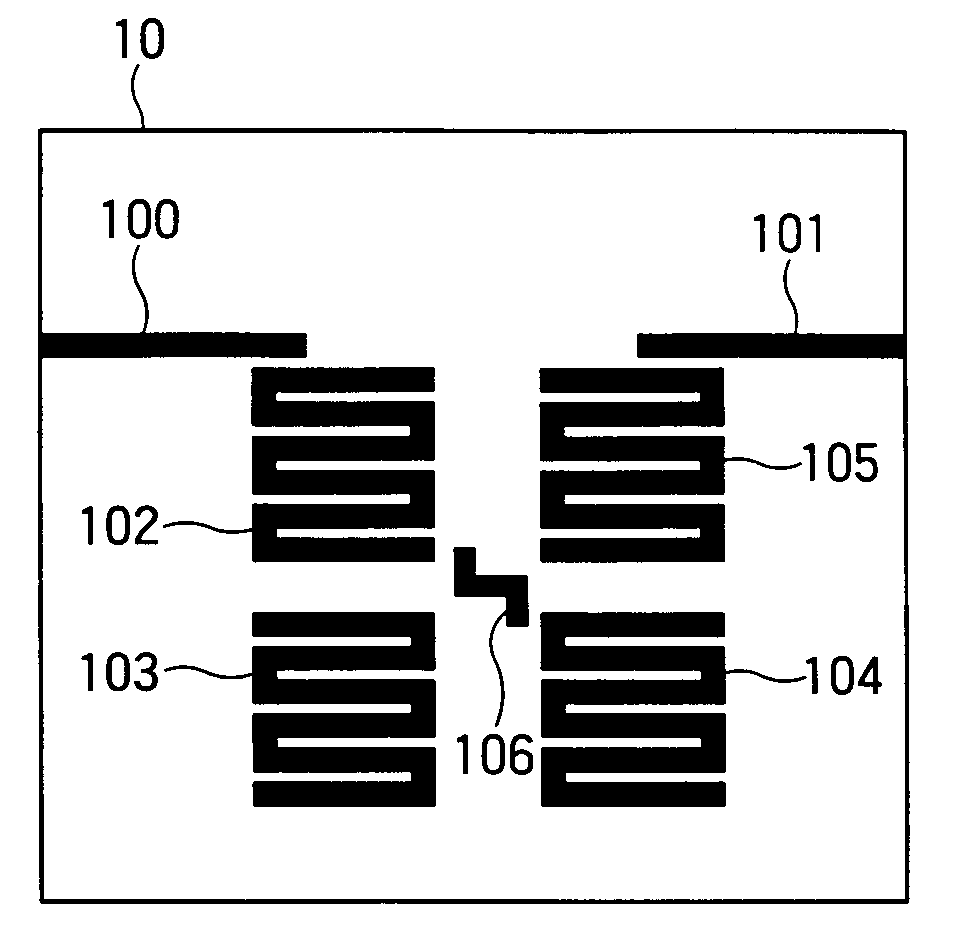
[0050]FIG. 1 shows a filter according to a first embodiment. A filter 10 is connected to the feed line by transmission lines of an input section 100 and an output section 101, and has four resonant elements 102, 103, 104 and 105. The resonant element is capable of taking various shapes such as a hairpin shape, an open loop shape, and a spiral shape in addition to a meander line shape as shown in FIG. 1. Further, the input and output sections is able to connect the resonant elements directly.

[0051] The filter 10 has a dense structure formed in such a manner that these resonant elements 102 to 105 are brought close to each other for miniaturization. The respective resonant elements 102 to 105 are constituted by bending an open ends microstrip line, and have an electrical length which is about an integer multiple of a half wavelength within a frequency range from fc−df / 2 to fc+df / 2, which is defined by a center frequency fc and a filter band width df according to a...

second embodiment

(2) SECOND EMBODIMENT

[0068]FIG. 8 shows a filter according to a second embodiment. A filter 60 is connected to the outside by transmission lines of an input section 600 and an output section 601, and is a six-orders filter consisting of six resonant elements 602, 603, 604, 605, 606 and 607. The resonant element has an open loop shape.

[0069] The filter 60 has a dense structure in which these resonant elements 602 to 607 are brought close to each other for miniaturization. The respective resonant elements 602 to 607 are constituted by bending an open ends microstrip line, and have an electrical length which is an integer multiple of a half wavelength within a frequency range from fc−df / 2 to fc+df / 2, which is defined by a center frequency fc and a filter band width df according to a filter specification.

[0070] In a block consisting of four resonant elements 603, 604, 605 and 606 which are selected from the six resonant elements 602, 603, 604, 605, 606 and 607, the four resonant eleme...

third embodiment

(3) THIRD EMBODIMENT

[0078]FIG. 9 shows a filter according to a third embodiment. A filter 70 is connected to the outside by transmission lines of an input section 700 and an output section 701, and is a eight-order filter consisting of eight resonant elements 702, 703, 704, 705, 706, 707, 708 and 709. The resonant element has an elliptic shape, and the filter 70 has a dense structure in which these resonant elements 702 to 709 are brought close to each other. Further, the filter 70 is constituted by two blocks of block 1 which consists of four resonant elements 702, 703, 704 and 705, and block 2 which consists of four resonant elements 706, 707, 708 and 709, and by making the resonant element 705 of the block 1 cascade-connected to the resonant element 706 of the block 2 by the gap coupling.

[0079] In the block 1, the four resonant elements are numbered counterclockwise from the resonant element 702 in the figure such that the resonant element 702 is designated as the first resonant...


PUM


Abstract

In resonant elements 102 to 105 constituting a resonant circuit, an uncontrolled cross coupling which exists between two resonant elements is controlled by using a coupling element 106 which is newly arranged between the resonant elements, whereby it is possible to create a state where two resonant elements are not coupled with each other or a state where the amount of the coupling is reduced, which states are difficult to be realized on a plane. As a result, it is possible to improve characteristics of a planar filter.

Description

CROSS REFERENCE TO RELATED APPLICATIONS [0001] This application is based upon and claims the benefit of priority from the prior Japanese Patent Applications No. 2006-143602, filed on May 24, 2006; the entire contents of which are incorporated herein by reference. BACKGROUND OF THE INVENTION [0002] 1. Field of the Invention [0003] The present invention relates to a resonant circuit, a filter circuit, and an antenna device. [0004] 2. Related Art [0005] A communication apparatus which performs information communication by radio or wire is constituted by various high frequency components such as an antenna, an amplifier, a mixer, and a filter. Among these components, a band pass filter (BPF), in which a plurality of resonant elements are arranged, has a function of passing only a signal in a specific frequency band. In today's communication systems, from a viewpoint of effective use of frequency, a sharp cut-off characteristic is preferred as a filter characteristic so as to enable the ...

Claims


Application Information

Patent Timeline
Patent Type & Authority Applications(United States)
IPC IPC(8): H01Q1/52H01P1/203H01P7/08
CPCH01P1/203H01Q21/065H01Q1/52H01Q1/38
Inventor KAWAGUCHI, TAMIOAIGA, FUMIHIKOKAYANO, HIROYUKISHIOKAWA, NORITSUGUHASHIMOTO, TATSUNORI
Owner KK TOSHIBA
Why Eureka
Try Eureka