Protective device for eyes
- Summary
- Abstract
- Description
- Claims
- Application Information
AI Technical Summary
Benefits of technology
Problems solved by technology
Method used
Image
Examples
example 1
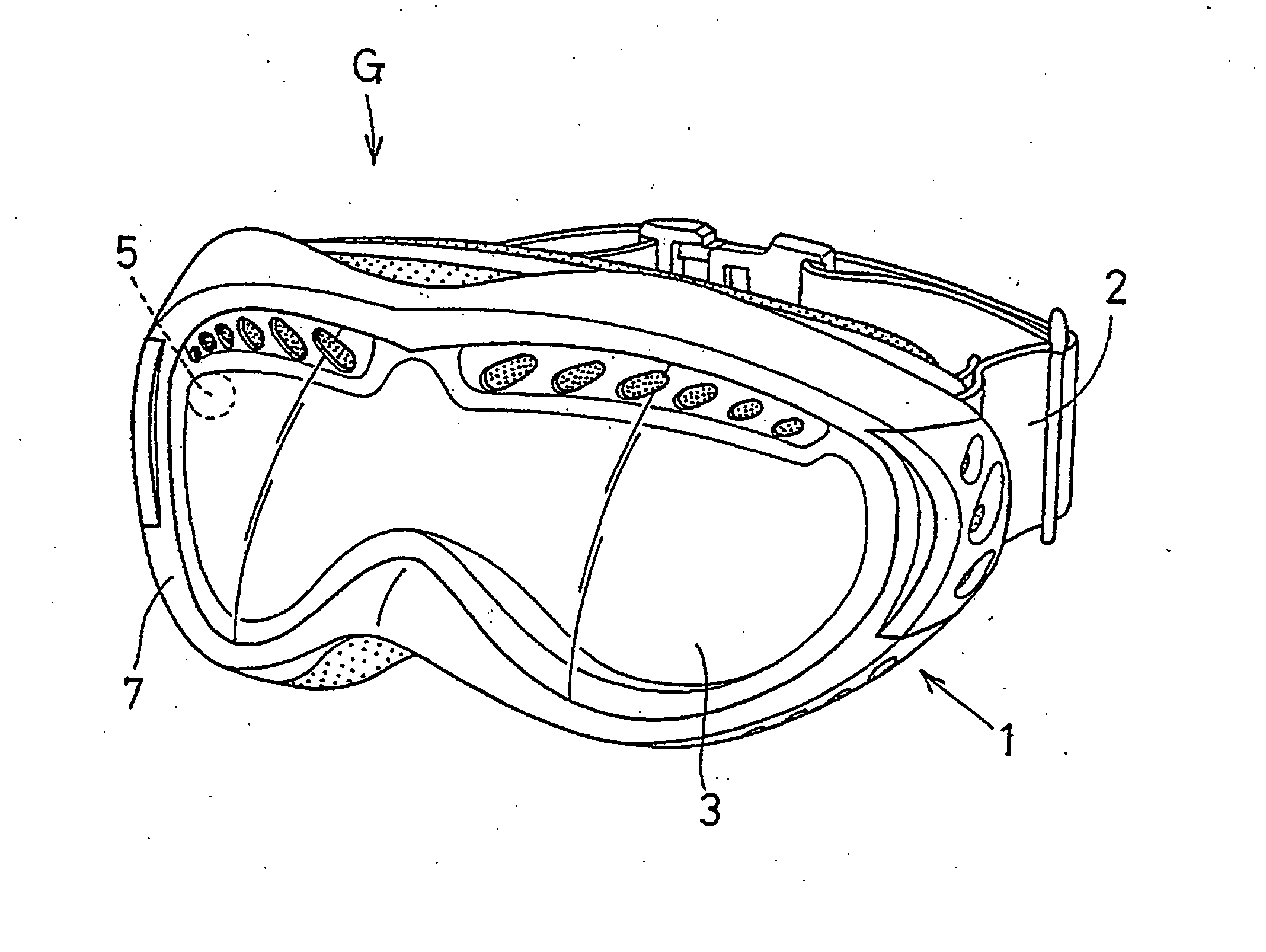
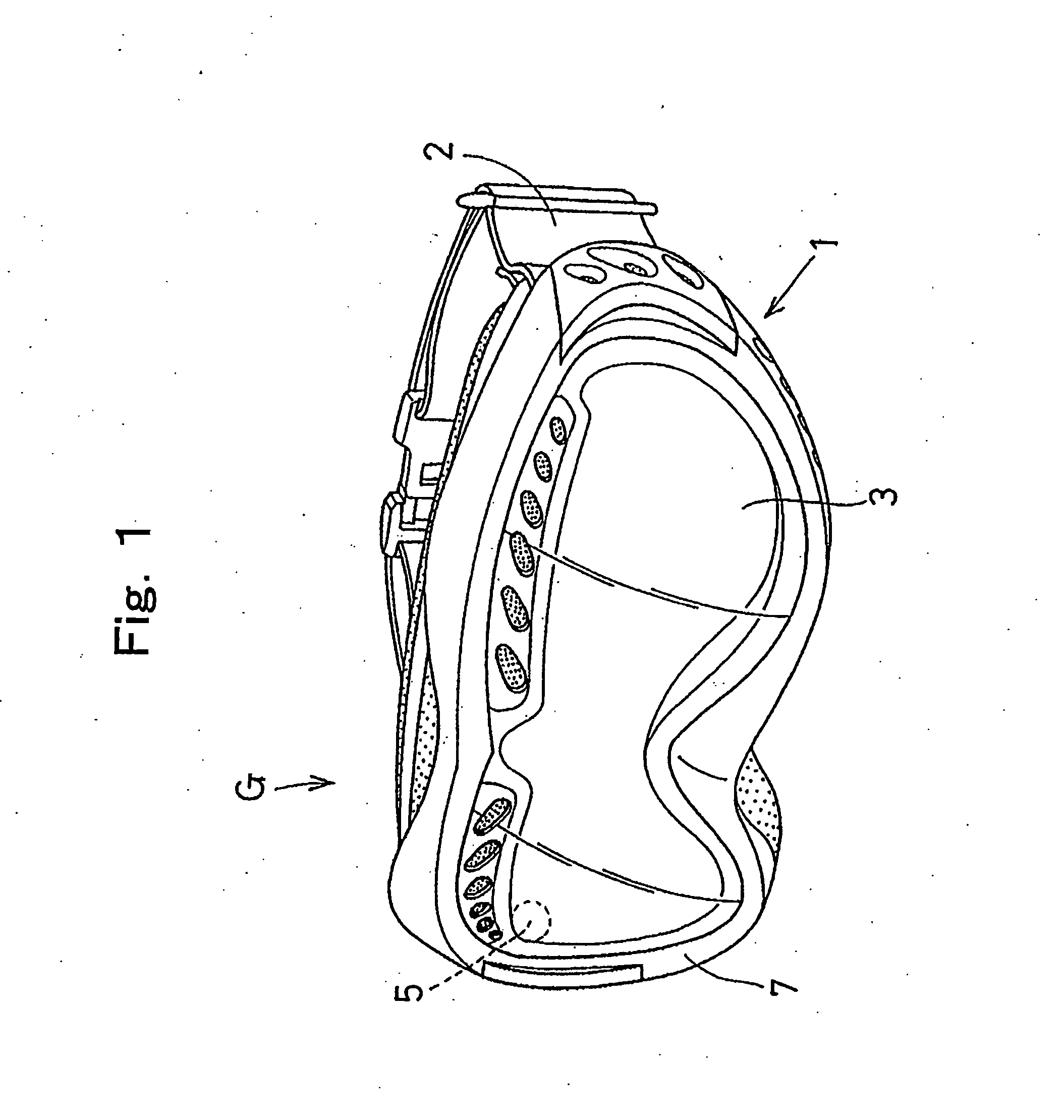
Preparation of Goggle
[0143] (1) Preparation of front lens: A bisphenol A type polycarbonate resin sheet with a viscosity average molecular weight of about 22,000 and thickness of 1 mm was punched into a size of a front lens.
[0144] The front curve side of the front lens was mirrored by a vacuum deposition technique.
[0145] (2) Preparation of back lens: A bisphenol A type polycarbonate resin sheet with a viscosity average molecular weight of about 22,000 and thickness of 0.8 mm was punched into a size of a back lens.
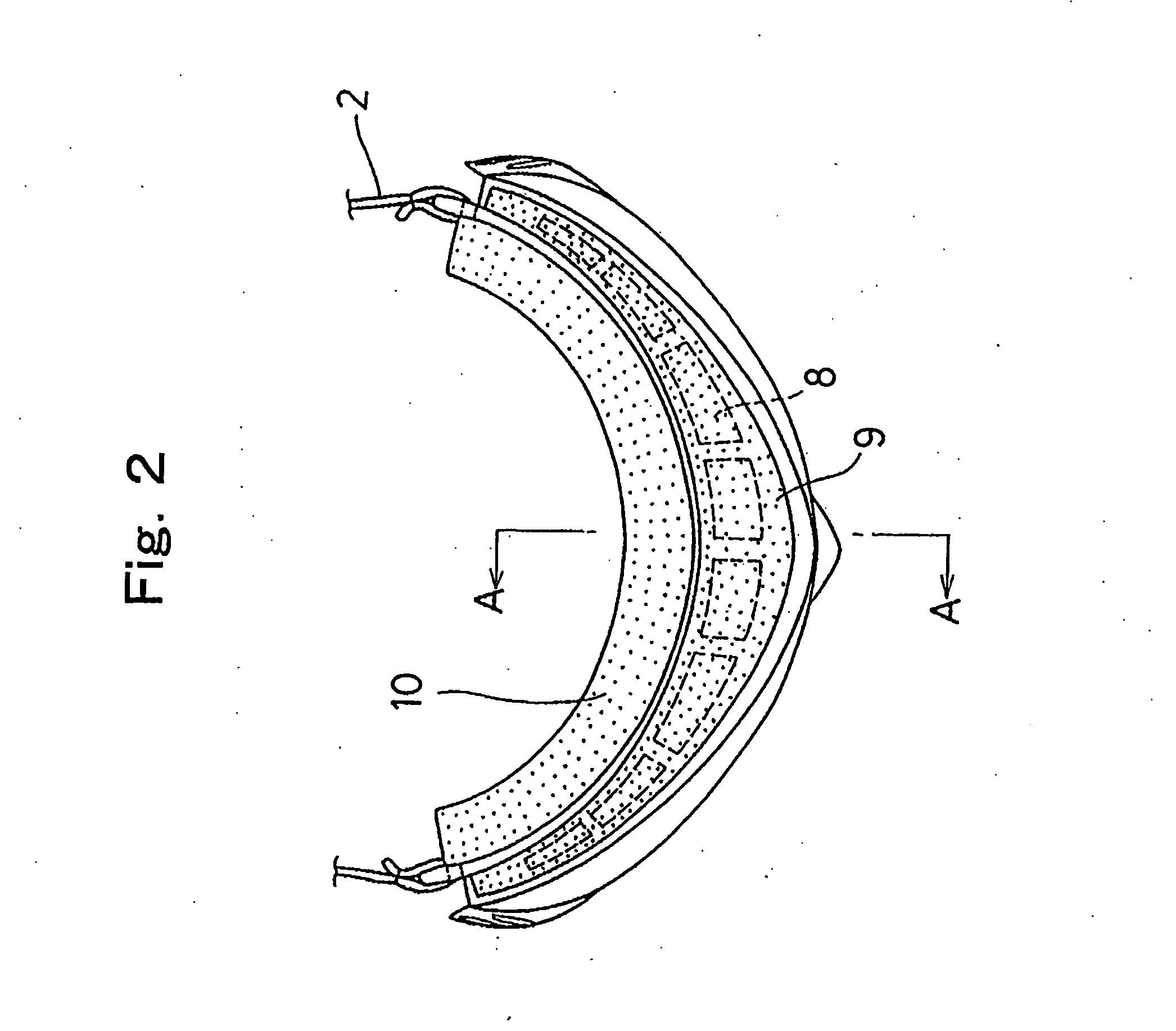
[0146] (3) Preparation of gasket: A closed-cell type porous sheet made of 3 mm-thick chloroprene was coated with a binding agent in both surfaces and covered with further a paper liner and the resulting sheet was punched into the corresponding shape of the double lens so as to be a ring-shaped gasket with width of 5 mm.
[0147] (4) Preparation of double lens: The back lens was set in a cylindrical die almost same as the shape of a double lens fitting hole of a goggle fra...
example 2
Preparation of Goggle
[0155] (1) Preparation of front lens: A front lens with a front curve of 6 base lens curve, a back curve of 6.1 base lens curve, and a center thickness of 1.8 mm was produced by injection molding of a bisphenol A type polycarbonate resin sheet with a viscosity average molecular weight of about 22,000.
[0156] The front curve side of the front lens was mirrored by a vacuum deposition technique.
[0157] (2) Preparation of back lens and pressure adjusting hole: A 0.8 mm-thick resin sheet made of a bisphenol A type polycarbonate resin with a viscosity average molecular weight of about 20,000 was punched into a size approximately close to that of a front lens.
[0158] A circular hole with a diameter of 1 mm was punched to make a pressure adjusting hole at the position of the back lens corresponding to the space surrounded with the front lens, a back lens, and a gasket when assembled and as near as possible to the gasket.
[0159] Successively, the above-mentioned resin s...
example 3
Preparation of Goggle
[0170] (1) Preparation of front lens: A front lens with a front curve of 6 base lens curve, a back curve of 6.1 base lens curve, and a center thickness of 1.8 mm was produced by injection molding of a transparent nylon resin (“Diamid” ZC 7500, manufactured by Daicel-Degussa, Ltd.).
[0171] The front curve side of the front lens was mirrored by a vacuum deposition technique.
[0172] (2) Preparation of back lens and pressure adjusting hole: A 1 mm-thick resin sheet made of the transparent nylon resin (“Diamid” ZC 7500, manufactured by Daicel-Degussa, Ltd.) was punched into a size approximately close to that of a back lens.
[0173] A circular hole with a diameter of 1 mm was punched to make a pressure adjusting hole at the position of the back lens corresponding to the space surrounded with the front lens, a back lens, and a gasket when assembled and as near as possible to the gasket.
[0174] Successively, the above-mentioned resin sheet was set in a die and thermally...
PUM
 Abstract
Description
Claims
Application Information
 - R&D
- Intellectual Property
- Life Sciences
- Materials
- Tech Scout
- Unparalleled Data Quality
- Higher Quality Content
- 60% Fewer Hallucinations
Browse by: Latest US Patents, China's latest patents, Technical Efficacy Thesaurus, Application Domain, Technology Topic, Popular Technical Reports.
© 2025 PatSnap. All rights reserved.Legal|Privacy policy|Modern Slavery Act Transparency Statement|Sitemap|About US| Contact US: help@patsnap.com


