Check patentability & draft patents in minutes with Patsnap Eureka AI!

Camera module

Inactive Publication Date: 2008-03-06
MITSUMI ELECTRIC CO LTD
View PDF5 Cites 9 Cited by
  • Summary
  • Abstract
  • Description
  • Claims
  • Application Information

AI Technical Summary

Benefits of technology

[0014]The present invention has been made in view of the problems described above, and therefore it is an object of the present invention to provide a camera module in which leaf springs can be attached to a holder easily and reliably.
[0016]According to the camera module of the present invention having the above structure, since the bonding operating of the upper and lower spring for the upper and lower cylindrical end portions of the holder using a synthetic resin that was performed in the conventional camera module can be omitted, it is possible to shorten a time necessary for manufacturing a camera module.
[0019]Further, in the camera module of the present invention, it is preferred that the lower cylindrical end portion of the holder is formed with a step so as to form a small cylindrical portion for receiving the inner annular portion and an end surface for supporting an upper surface of the inner annular portion, wherein the first means includes notches and tongues formed in the outer periphery of the inner annular portion of the lower leaf spring and protrusions formed on the end surface of the lower cylindrical end portion so as to be engageable with the respective tongues by rotating the lower leaf spring, and wherein the second means include holding means provided on the lower cylindrical end portion of the holder for holding the inner annular portion side end parts of the respective bridge portions of the leaf spring from the bottom thereof in a state that the upper surface of the inner annular portion is supported on the end surface of the step and for restricting further rotation of the lower leaf spring in a state that the protrusions are engaged with the tongues.
[0024]Moreover, in the camera module of the present invention, it is preferred that the ring-shaped member is a stopper for restricting excessive displacement of the holder in an upward direction.

Problems solved by technology

However, the width of the end surface of the cylindrical end portion is extremely narrow.
Therefore, an application of the synthetic resin to the end surface must be carried out carefully, and thus there is a problem in that a time required for the application operation cannot be shortened.
This leads to another problem in that a time required for manufacturing the camera module cannot be shortened.
Furthermore, in the case where a bonding area, that is an area of the end surface of the holder is extremely small, or in the case where a bonding condition of the synthetic resin against the inner annular portion of the leaf spring is not sufficient, it is not possible to ensure a sufficient bonding strength therebetween.
In such a case, there is a problem in that the upper leaf spring 104 and / or the lower leaf spring 110 may be partially peeled off from the holder 108 due to the reduced bonding force in the event that the electronic apparatus equipped with the camera module is dropped by accident.

Method used


Image

  • Camera module
  • Camera module
  • Camera module

Examples


Embodiment Construction

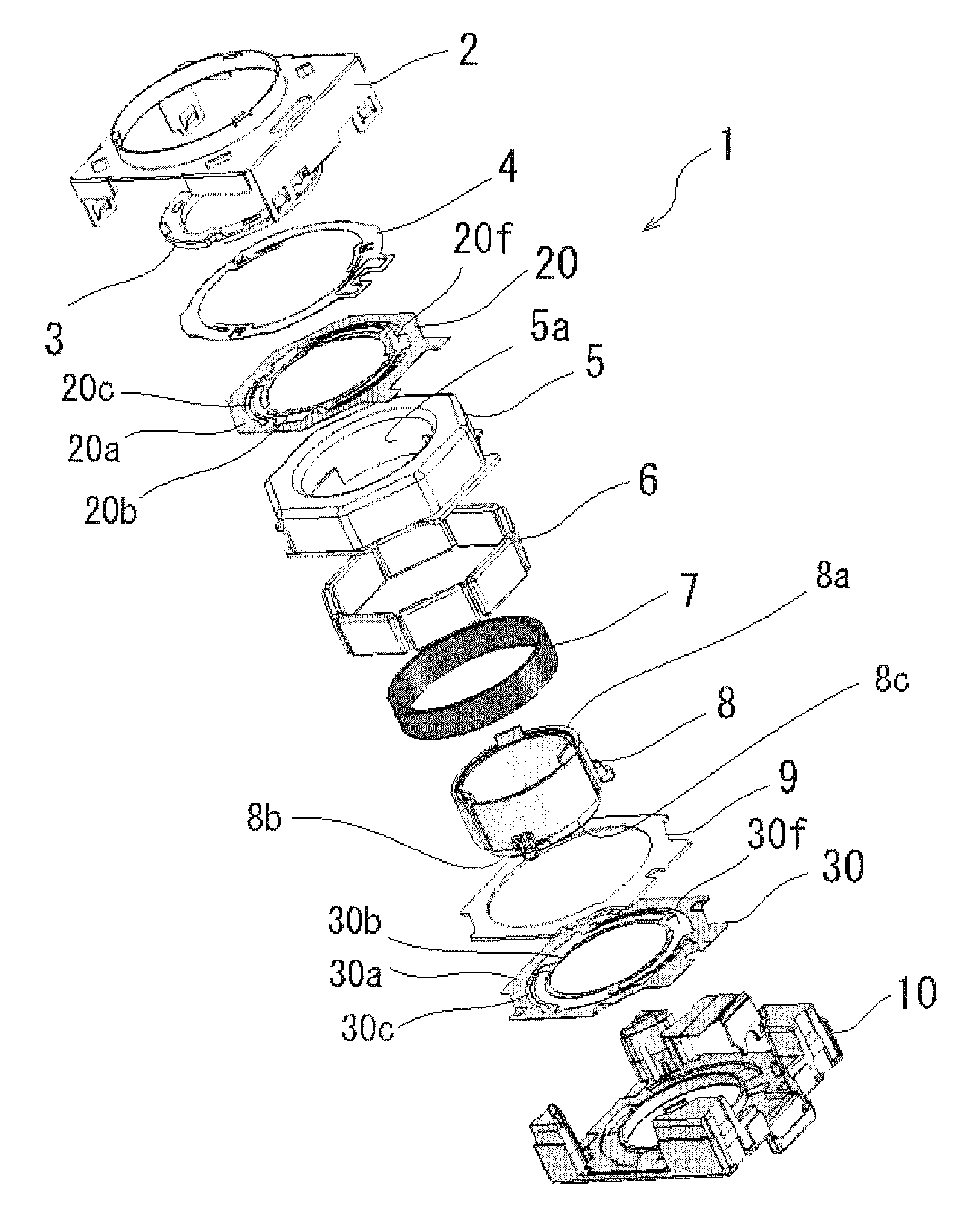
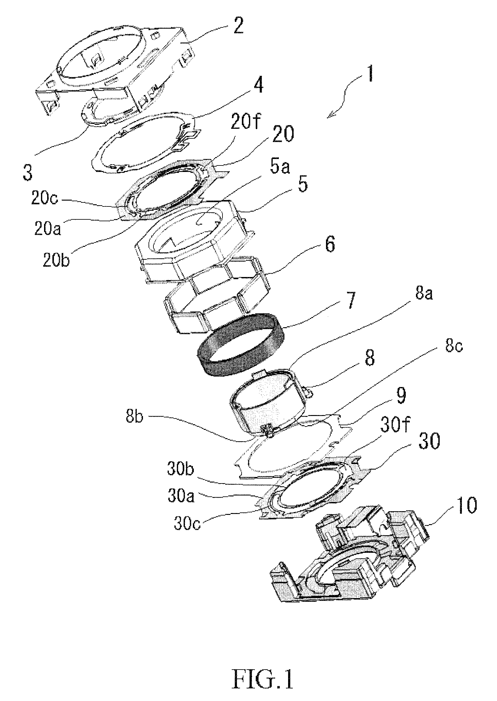
[0036]A camera module according to an embodiment of the present invention will be described below with reference to the accompanying drawing.

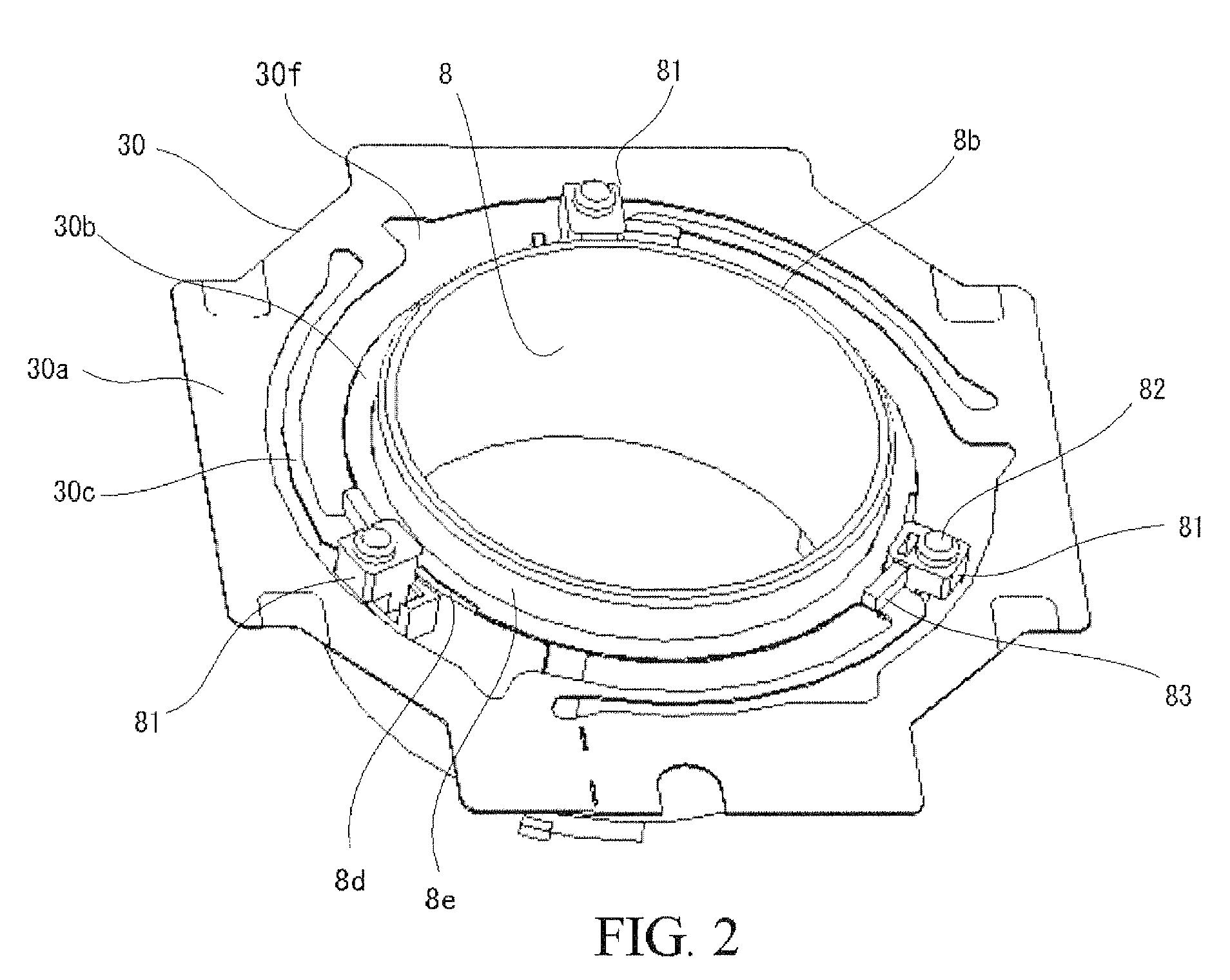
[0037]The camera module according to the embodiment comprises: a lens unit (not shown) which constitutes an optical system of the camera module; a holder 8 which houses the lens unit and is displaceable along an optical axis direction of the lens unit, the holder 8 having a cylindrical shape having upper and lower cylindrical end portions 8a and 8b; a coil 7 provided on the holder 8; a yoke 5 and magnets 6 provided on the yoke 5 for providing a magnetic field to the coil 7; upper and lower leaf springs 20, 30 for supporting the holder 8 so that the holder 8 is displaceable along an optical axis direction of the lens unit, each of the upper and lower springs 20, 30 including an outer annular portion 20a (30a), an inner annular portion 20b (30b) provided inside the outer annular portion 20a, (30a) and attached to one of the cylindrical end portio...


PUM


Abstract

A camera module having a holder including a leans unit and upper and lower leaf springs for displaceably supporting is provided. Each of the leaf springs has an outer annular portion, an inner annular portion, and bridge portions couple between the outer annular portion and the inner annular portion for resiliently support the inner annular portion with respect to the outer annular portion. The inner annular portion of the lower leaf spring is attached to an lower cylindrical end portion of the holder mechanically and reliably, and the inner annular portion of the upper leaf spring is attached to the upper cylindrical end portion of the holder in a state that the inner annular portion is fixedly held between an upper cylindrical end portion of the holder and a stopper. According to the camera module having the above structure, since the bonding operating using a synthetic resin that was performed in the conventional camera module can be omitted, it is possible to shorten a time necessary for manufacturing a camera module.

Description

BACKGROUND OF THE INVENTION[0001]1. Field of the Invention[0002]This invention relates to a camera module, and more specifically to a camera module that can be used in small-sized electronic apparatuses such as digital cameras, camera-equipped cellular phones and the like.[0003]2. Description of the Prior Art[0004]A camera module having a function of displacing a lens unit in a direction of an optical axis of the lens unit is used in relatively small-sized digital cameras, camera-equipped cellular phones and the like. This function is used for providing an autofocus function and / or zoom function and the like, and is achieved by an interaction between a magnetic field generated by an electrical current flowing in a coil and a magnetic field generated by a yoke and magnets provided on the yoke.[0005]Such a camera module includes a barrel which holds the lens unit, a holder which houses the barrel therein, and a pair of leaf springs for supporting the holder so that the holder is displ...

Claims


Application Information

Patent Timeline
IPC IPC(8): G02B7/04
CPCG02B7/023H04N5/2257H04N5/2254G03B3/10H04N23/57H04N23/55
Inventor ISHIZAWA, TAKASHIOSAKA, TOMOHIKO
Owner MITSUMI ELECTRIC CO LTD
Features
  • R&D
  • Intellectual Property
  • Life Sciences
  • Materials
  • Tech Scout
  • Unparalleled Data Quality
  • Higher Quality Content
  • 60% Fewer Hallucinations
Learn More