Sealing arrangement for the attachment of a side plate of a centrifugal pump and an attachment screw used therewith

a technology of side plates and attachment screws, which is applied in the direction of screws, nuts, bolts, etc., can solve the problems of liquid to be pumped leakage, reduced pump efficiency, and increased clearance of front walls of volutes, so as to improve the competitiveness, increase the cost of acquisition, and improve the structure of invention.

a technology of side plates and attachment screws, which is applied in the direction of screws, nuts, bolts, etc., can solve the problems of liquid to be pumped leakage, reduced pump efficiency, and increased clearance of front walls of volutes, so as to improve the competitiveness, increase the cost of acquisition, and improve the structure of invention.

US20080056846A1Active Publication Date: 2008-03-06SULZER MANAGEMENT AG

Image

  • Sealing arrangement for the attachment of a side plate of a centrifugal pump and an attachment screw used therewith
  • Sealing arrangement for the attachment of a side plate of a centrifugal pump and an attachment screw used therewith
  • Sealing arrangement for the attachment of a side plate of a centrifugal pump and an attachment screw used therewith

Examples


Embodiment Construction

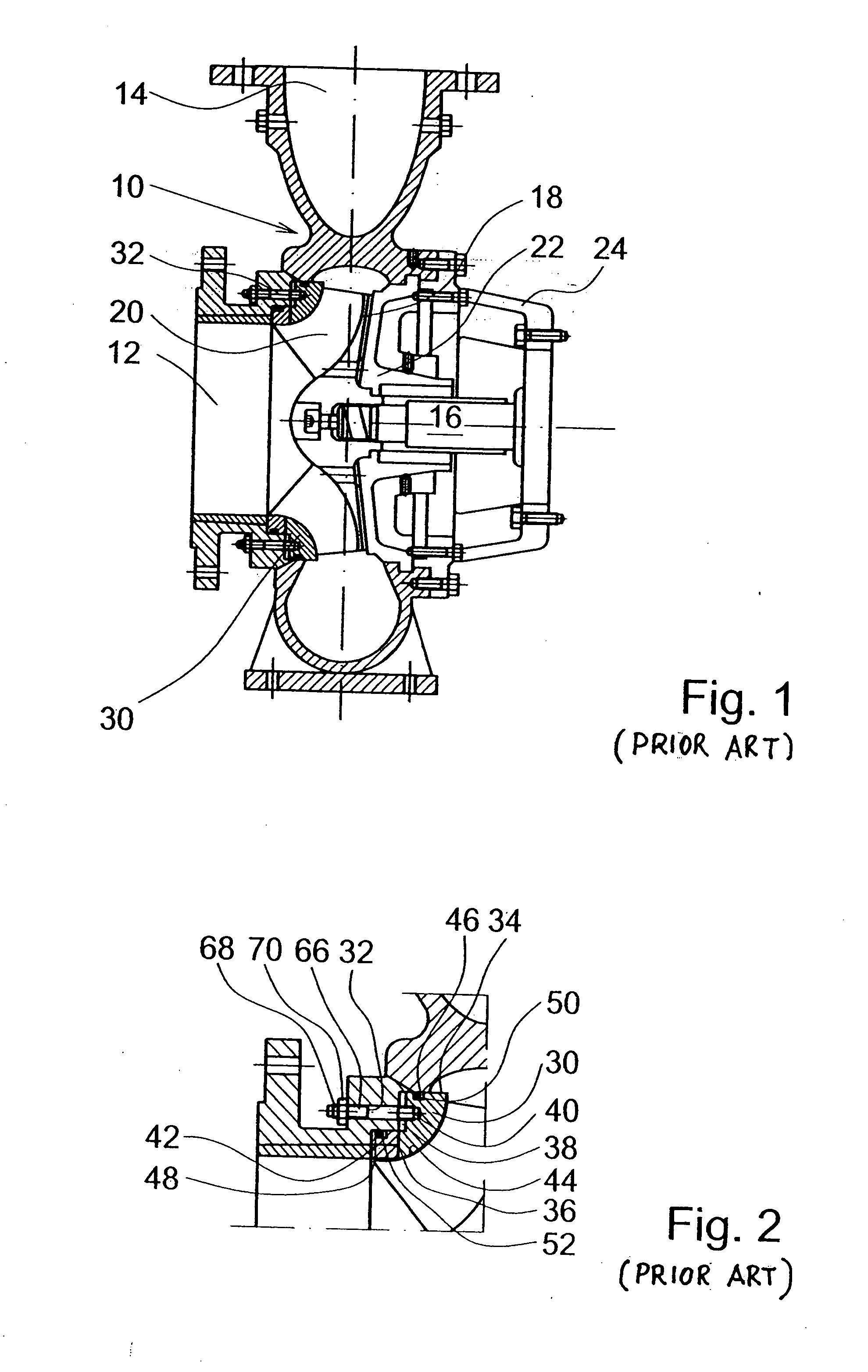
[0015] According to FIG. 1, a centrifugal pump in accordance with the prior art comprises a volute 10 with a suction opening 12 and a pressure opening 14, an impeller 18 with working vanes 20 located on a shaft 16 inside the volute 10, a pump rear wall 22 and a pump casing 24 with bearings. The drawing also illustrates a so-called adjustable side plate 30 of the volute 10, attached to the volute preferably with at least three adjustment screws 32.

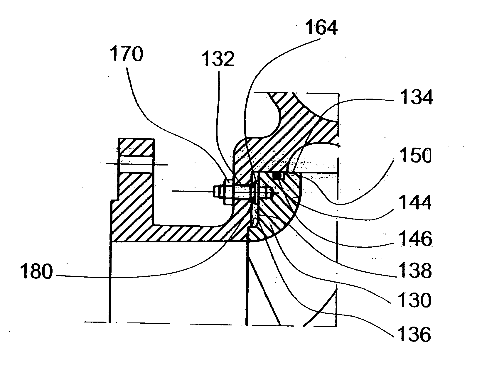
[0016]FIG. 2 illustrates the structure and attachment of the side plate 30 in accordance with prior art more in detail. The side plate 30 is an annular member with two radially outwards opening cylindrical surfaces 34 and 36. The surface 34 is located at the outer rim of the side plate 30 and guides the side plate 30 inside a larger cylindrical surface of the volute 10 within a small clearance therefrom. A second cylindrical surface 36 of the side plate 30 with a smaller diameter is located against a corresponding cylindrical surface of th...


PUM


Abstract

The present invention relates to a sealing arrangement for attaching a side plate often used with a pump volute of a centrifugal pump and an attachment screw used therewith. A characterizing feature of the sealing arrangement for attaching the side plate of a centrifugal pump, comprising at least a pump volute (10) and a side plate (130) with attachment screws (132) and flanges (164) of the screws (132) arranged in communication with the volute (10) or the cover of the casing, is that an annular seal (180) is arranged between the screw (132) and the volute or the cover of the casing.

Description

RELATED APPLICATIONS [0001] This application is a divisional of copending application Ser. No. 11 / 413,272 filed Apr. 28, 2006 which claims the priority of Finnish Patent Application No. 20050451 filed Apr. 29, 2005, the disclosures of both being incorporated herein by reference as if fully set forth herein.BACKGROUND OF THE INVENTION [0002] The present invention relates to a sealing arrangement for the attachment of a side plate often used in connection with a pump volute of a centrifugal pump and an attachment screw used therewith. [0003] A centrifugal pump comprises, as known, mainly a so-called volute with a suction opening, a discharge opening, and an impeller rotating inside the volute. Since the efficiency and capacity of the pump are substantial both for the manufacturer, seller and especially for the end user, the clearances between the impeller and the volute must be optimal, in other words in most cases as small as possible. By using modern production methods, it is possib...

Claims


Application Information

Patent Timeline
06 Mar 2008
Publication
US20080056846A1
IPC
F16B35/00; F04D29/16
CPC
F04D29/167; F04D29/622
Inventors
AHLROTH, JUSSI; LEHTONEN, JORMA