Adjustment system for a speed reduction belt assembly

a technology of automatic adjustment and speed reduction, which is applied in the direction of conveyors, conveyor parts, discharging equipment, etc., can solve the problems of lost production and costly delays

Active Publication Date: 2008-03-06
LES PRODN GIBERGO
View PDF14 Cites 10 Cited by
  • Summary
  • Abstract
  • Description
  • Claims
  • Application Information

AI Technical Summary

Benefits of technology

[0011]Also in a preferred embodiment, the vertical adjustment mechanism includes first and second vertical supports for supporting the first and second ends of the belt assembly, respectively. The first vertical support is preferably hingedly connected...

Problems solved by technology

Improperly received planks can collide or land on each other and cause jams and equipment breakdowns, resulting in lost production and costly delays.
Such adjustments are usuall...

Method used


Image

  • Adjustment system for a speed reduction belt assembly
  • Adjustment system for a speed reduction belt assembly
  • Adjustment system for a speed reduction belt assembly

Examples


Embodiment Construction

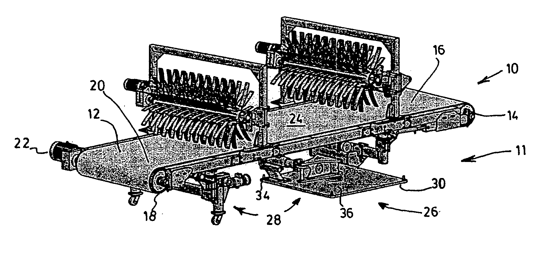
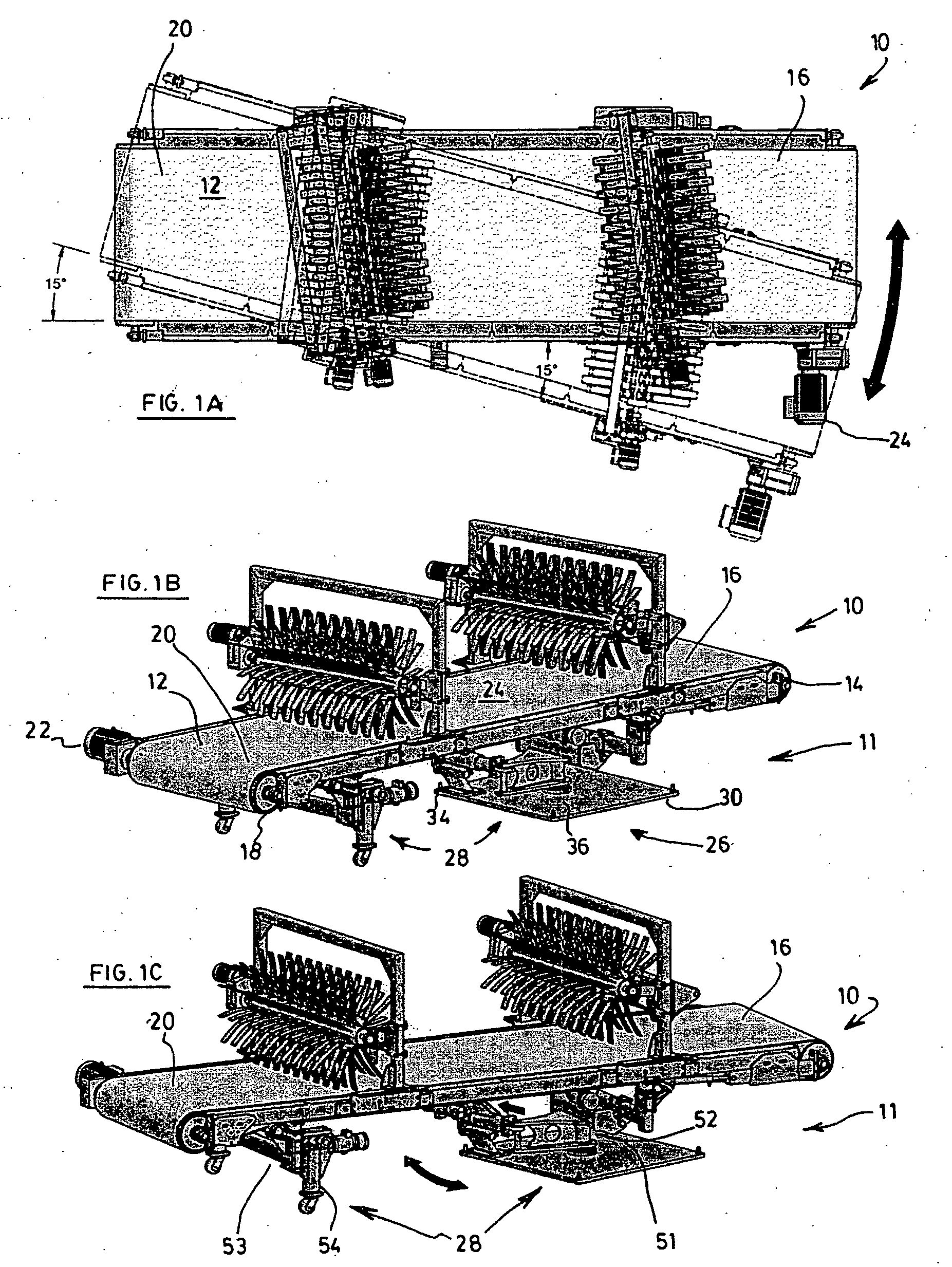
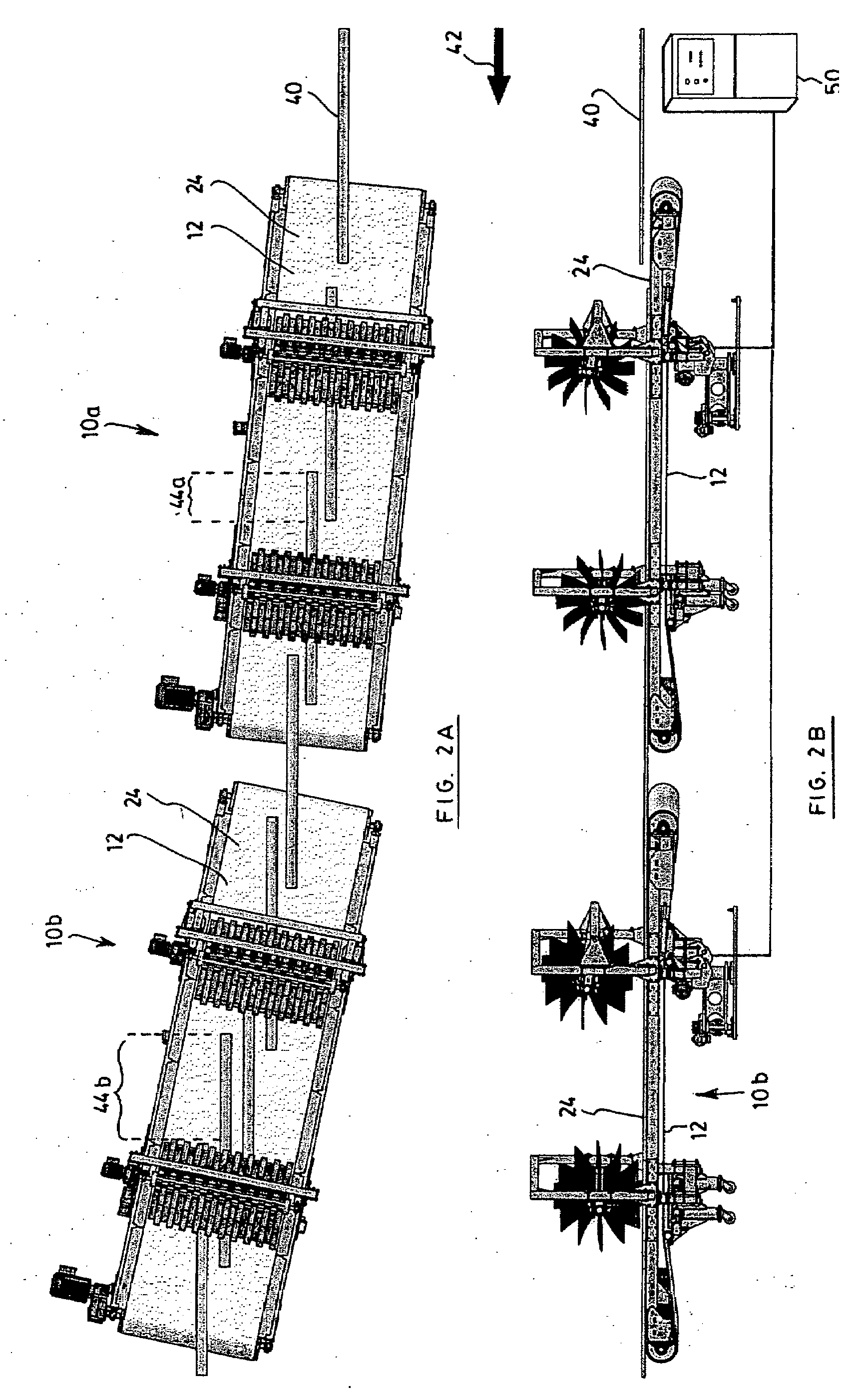
[0024]In the following description, the same numerical references refer to similar elements. The embodiments shown in the figures are preferred, for exemplification purposes only.

[0025]In the context of the present description, the expression “lumber” includes all types of elongated wood products, as apparent to a person skilled in the art. For this reason, the expressions “plank” or “article”, for example, should not be taken as to limit the scope of the present invention and includes all other kinds of usages or items with which the present invention may be used and could be useful.

[0026]In addition, although the preferred embodiments of the present invention as illustrated in the accompanying drawings include various components, etc., and although the preferred embodiments of the speed reduction belt assembly and corresponding parts of the present invention as shown consist of certain geometrical configurations as explained and illustrated herein, not all of these components and ...


PUM


Abstract

An automated adjustment system is provided for positioning a speed reduction belt assembly to receive an elongated wood article exiting a processing machine. The speed reduction belt assembly has opposite first and second ends. The automated adjustment system includes a horizontal adjustment mechanism operable to adjust an angle of the speed reduction belt assembly in a horizontal plane. The automated adjustment system also includes a vertical adjustment mechanism operable to adjust the height of one of the first and second ends of the belt assembly relative to the other of the first and second ends of the belt assembly, thereby adjusting an inclination of the belt assembly. The automated adjustment system further includes a control unit in communication with the horizontal and vertical adjustment mechanisms for sending control signals thereto. The control signals determine the angle and inclination of the belt assembly.

Description

FIELD OF THE INVENTION[0001]The present invention relates to wood processing machinery. More particularly, the present invention concerns an automated adjustment system for a speed reduction belt assembly.BACKGROUND OF THE INVENTION[0002]In the wood processing industry, it is common for modern planers to operate at speeds of 3000 feet per minute. It is known to position a speed reduction belt assembly in front of such a planer, or other processing machine of a similar type, in order to receive an elongated article, such as a plank of wood, as it exits the processing machine in order to slow down the planed wooden plank.[0003]A speed reduction belt assembly typically provides a continuous surface traveling at a lower speed in order to receive the wooden planks as they exit the planer and thereby reduce the speed of the planks so that they may be transferred for further processing, or stacked for storage or shipping.[0004]Typically, a conventional speed reduction belt assembly normall...

Claims


Application Information

Patent Timeline
IPC IPC(8): F16H7/22
CPCB27B31/08B65G2201/0282B65G21/12B27C1/12
Inventor GILBERT, SYLVAINPARE, DANIEL
Owner LES PRODN GIBERGO
Why Eureka
Try Eureka