
Flow Based Pressure Isolation and Fluid Delivery System Including Flow Based Pressure Isolation and Flow Initiating Mechanism

a technology of flow based pressure isolation and fluid delivery system, which is applied in the direction of catheters, angiography, diagnostic recording/measuring, etc., can solve the problems of many pressure transducers being damaged, manifolds not allowing contrast injection, and operator effort often leading to fatigu

Active Publication Date: 2008-03-06
BAYER HEALTHCARE LLC
View PDF32 Cites 99 Cited by
  • Summary
  • Abstract
  • Description
  • Claims
  • Application Information

AI Technical Summary

Benefits of technology

[0020] One or both of the valve member and internal cavity may be shaped to permit fluid flow between the inlet port and isolation port in the open position and prevent fluid flow between the inlet port and isolation port in the closed position. Moreover, a volumetric capacitance element may be disposed in the internal cavity.
[0025] One or both of the valve member and internal cavity may be shaped to permit fluid flow between the inlet port and isolation port in the open position and prevent fluid flow between the inlet port and isolation port in the closed position. Moreover, a volumetric capacitance element may be disposed in the internal cavity.
[0026] The protection of a pressure transducer may take the form of a method in another embodiment disclosed herein. The flow-based pressure isolation method protects a pressure transducer from fluid pressure damage using the pressure isolation mechanism summarized hereinabove. The pressure isolation mechanism comprises an inlet port, an isolation port, and an internal cavity wherein a free floating, fluid flow responsive valve member is disposed and adapted to engage a seal seat in the internal cavity. An optional flow initiating mechanism may be associated with the isolation port. The method generally comprises associating the pressure transducer with the isolation port; placing a pressurizing device for delivering fluid under pressure in fluid connection with the inlet port; actuating the pressurizing device to cause fluid flow in the inlet port such that the free floating, fluid flow responsive valve member engages the seal seat to attain a substantially closed position and prevent fluid flow between the inlet port and isolation port. In a variation of the foregoing method, upon actuation of the pressure device, the flow initiating mechanism may initiate flow around the valve member such that the valve member operates to the closed position substantially upon flow initiation.

Problems solved by technology

Thus, manual sources of fluid pressure and flow used in medical applications, such as syringes and manifolds, typically require operator effort that provides feedback of the fluid pressure / flow generated to the operator.
The feedback is desirable, but the operator effort often leads to fatigue.
Specifically, many pressure transducers can be damaged if they are subjected to pressures as low as about 75 psi.
Accordingly, this configuration provided by some currently available manifolds does not allow contrast injection to be made while the pressure transducer is in communication with the catheter.
One problem associated with the foregoing valve-manifold design is that the operator often forgets to turn the stopcock back to the position where the pressure transducer is in fluid communication with the catheter.
As a result, the monitoring of the vessel or artery is interrupted for time periods longer than necessary.
Accordingly, when the operator fails to turn the stopcock handle, other members of the medical team must interrupt the operator and tell him or her to turn the pressure transducer back on which may cause an unnecessary distraction during a delicate medical procedure.

Method used


Image

  • Flow Based Pressure Isolation and Fluid Delivery System Including Flow Based Pressure Isolation and Flow Initiating Mechanism
  • Flow Based Pressure Isolation and Fluid Delivery System Including Flow Based Pressure Isolation and Flow Initiating Mechanism
  • Flow Based Pressure Isolation and Fluid Delivery System Including Flow Based Pressure Isolation and Flow Initiating Mechanism

Examples


third embodiment

[0085] pressure isolation mechanism 100b is shown in FIGS. 8-12. Pressure isolation mechanism 100b operates in an analogous manner to pressure isolation mechanisms 100, 100a discussed hereinabove but includes several structural differences over these embodiments. Initially, it is noted that housing body 102b is still desirably provided as a two-piece structure including first or upper housing portion 104b and second or lower housing portion 106b, which are adapted to connect together to form the housing body 102b. However, second or lower housing portion 106b is now formed with a central recess 144 which is adapted to receive and accept a depending annular element 146 associated with the first or upper housing portion 104b. The insertion of annular element 146 within central recess 144 may be configured as a friction fit engagement to secure the connection first and second housing portions 104b, 106b. In this embodiment, a suitable medical grade adhesive is desirably used to secure ...

fourth embodiment

[0089] pressure isolation mechanism 100c is shown in FIGS. 13-16. Pressure isolation mechanism 100c operates in an analogous manner to pressure isolation mechanisms 100, 100a, 100b discussed hereinabove and has the outward appearance of pressure isolation mechanism 100b discussed immediately above. As with pressure isolation mechanism 110b, housing body 102c is desirably provided as a two-piece structure including first or upper housing portion 104c and second or lower housing portion 106c, which are adapted to connect together to form the housing body 102b. As with the immediately foregoing embodiment, second or lower housing portion 106c is now formed with central recess 144c which is adapted to receive and accept depending annular element 146c associated with the first or upper housing portion 104c. The engagement of annular element 146c within central recess 144c may again be configured as a friction fit engagement to secure the connection first and second housing portions 104c,...


PUM


Abstract

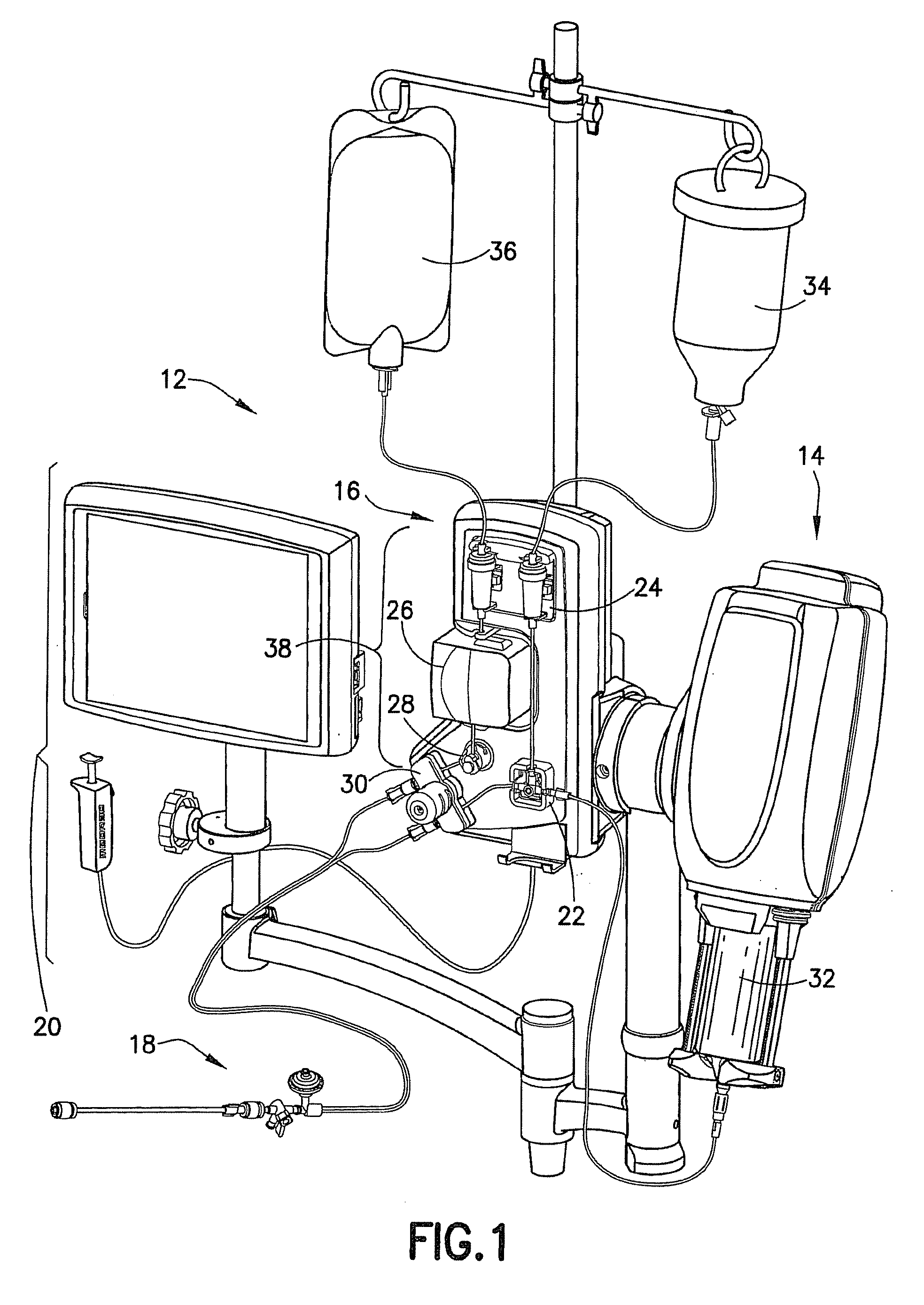
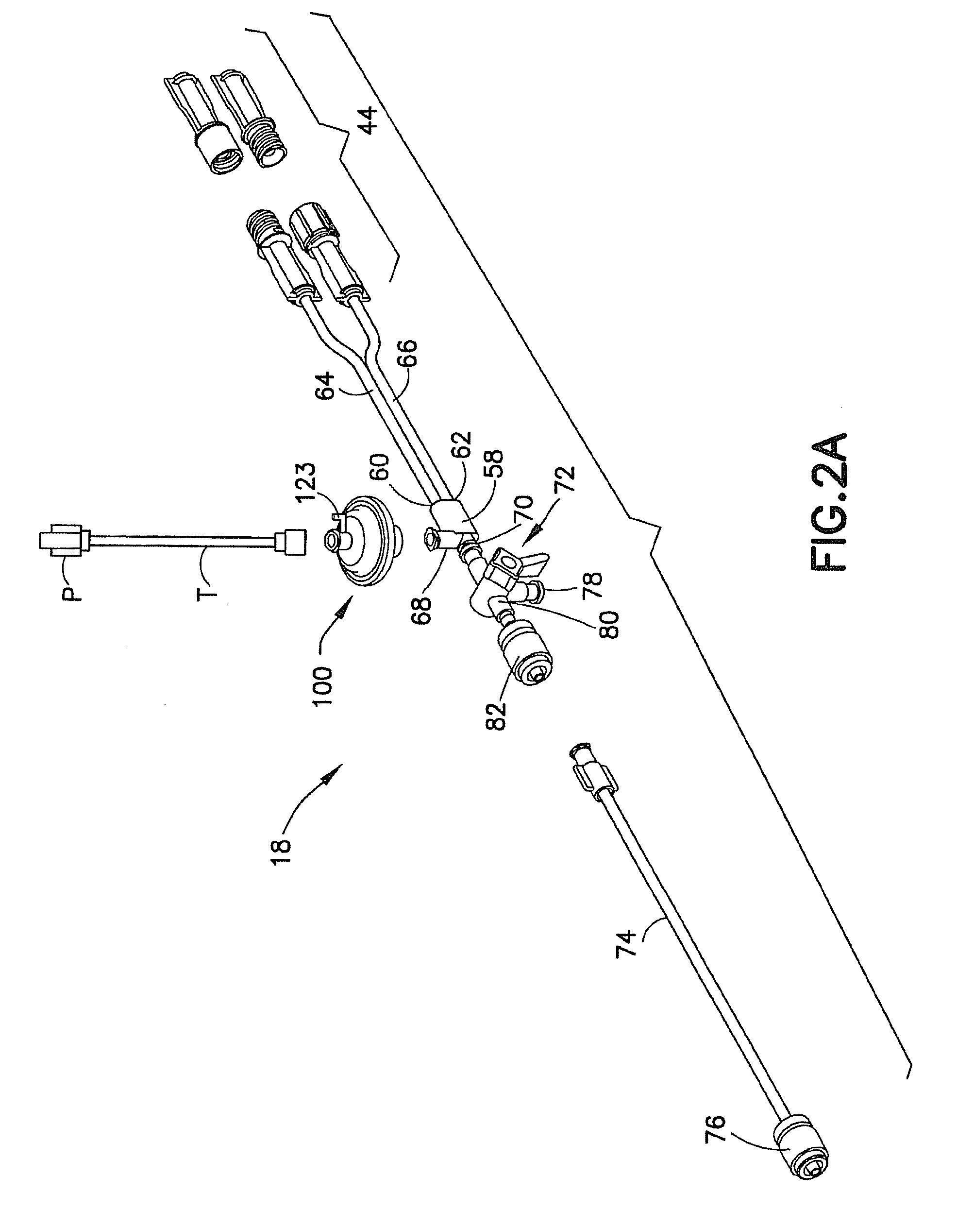
The fluid delivery system includes a pressurizing device for delivering a pressurized injection fluid, a low pressure fluid delivery system, and a pressure isolation mechanism adapted for fluid communication with the pressurizing device and low pressure fluid delivery system. The pressure isolation mechanism includes a housing defining an inlet port, an isolation port, and an internal cavity. The housing defines a seal seat in the internal cavity between the inlet port and isolation port. A valve member is disposed in the internal cavity. The valve member is free floating in the internal cavity and is adapted to engage the seal seat. The valve member has an open position permitting fluid communication between the inlet port and isolation port, and is fluid flow responsive to fluid flow in the inlet port to engage the seal seat and attain a closed position preventing fluid flow between the inlet port and isolation port.

Description

RELATED APPLICATIONS [0001] This application is a continuation-in-part application of application Ser. No. 11 / 615,371, filed Dec. 22, 2006, entitled “Flow Based Pressure Isolation and Fluid Delivery System Including Flow Based Pressure Isolation”. [0002] This application may contain subject matter that is related to that disclosed in the following co-pending applications: application Ser. No. 11 / 551,027, filed Oct. 19, 2006 entitled “Fluid Delivery System, Fluid Path Set, and Pressure Isolation Mechanism with Hemodynamic Pressure Dampening Correction” which is a continuation-in-part of application Ser. No. 11 / 004,670, filed Dec. 3, 2004, entitled “Fluid Delivery System Including a Fluid Path Set with Sterile Check Valve Connector” which is a continuation-in-part of application Ser. No. 10 / 826,149, filed Apr. 16, 2004, entitled “Fluid Delivery System, Fluid Path Set, Sterile Connector and Improved Drip Container and Pressure Isolation Mechanism” which may contain subject matter that ...

Claims


Application Information

Patent Timeline
IPC IPC(8): A61M5/155F16K31/12
CPCA61M2205/581A61M39/24A61M2039/248A61M2205/583A61M2039/2433A61M5/007A61M5/1408A61M5/1684A61M5/16831A61M5/16827A61M2205/3306A61M2005/1403A61M2205/3362A61M2039/2473A61M2039/2453A61M5/365A61M5/14546Y10T137/0352Y10T137/7758Y10T137/7871Y10T137/7915Y10T137/85978Y10T137/87829A61B5/02141A61B5/0215A61M5/142A61M5/16881A61M5/172A61M2039/229
Inventor SPOHN, MICHAEL A.HAURY, JOHN A.
Owner BAYER HEALTHCARE LLC
Features
  • Generate Ideas
  • Intellectual Property
  • Life Sciences
  • Materials
  • Tech Scout
  • Unparalleled Data Quality
  • Higher Quality Content
  • 60% Fewer Hallucinations
Learn More