Cylinder block and internal combustion engine

a technology of cylinder block and internal combustion engine, which is applied in the direction of engine cooling apparatus, cylinder, liquid cooling, etc., can solve the problem of excessive cooling effect in the opening-side area of the cylinder block, and achieve the effect of reducing the temperature difference and circulating amoun

Inactive Publication Date: 2008-03-13
TOYOTA JIDOSHA KK +1
View PDF9 Cites 22 Cited by
  • Summary
  • Abstract
  • Description
  • Claims
  • Application Information

AI Technical Summary

Benefits of technology

[0026]In an internal combustion engine where the path that connects the water pump to the coolant passage in the cylinder head differs from the path that connects the water pump to the water jacket, the flow amount of coolant flowing in the water jacket per unit time is generally small, as compared to an internal combustion engine where the water pump is connected to the coolant passage and the water jacket via the same path, that is, an internal combustion engine where all the coolant supplied to the coolant passage passes through the water jacket. Therefore, the difference in the cooling effect between the opening-side area of the cylinder block and the opposite opening-side area of the cylinder block is likely to be large. Accordingly, the temperature difference between the opening-side area and the opposite opening-side area is also likely to be large.
[0027]With the above-described configuration, it is possible to appropriately reduce the temperature difference between the opening-side area of the cylinder block and the opposite opening-side area of the cylinder block in the internal combustion engine.

Problems solved by technology

Thus, the cooling effect is likely to be excessively large in the opening-side area of the cylinder block.

Method used


Image

  • Cylinder block and internal combustion engine
  • Cylinder block and internal combustion engine
  • Cylinder block and internal combustion engine

Examples


Embodiment Construction

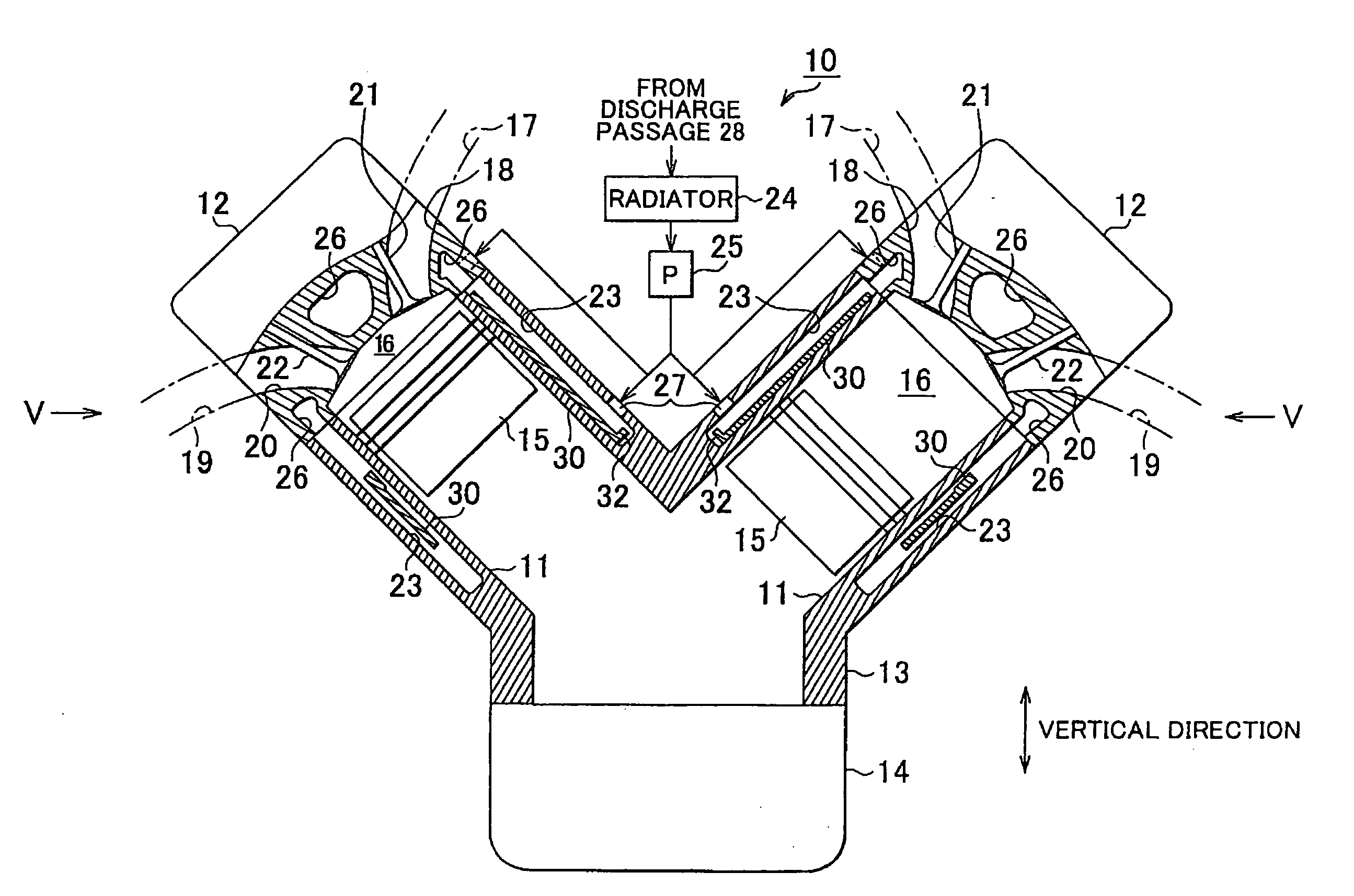
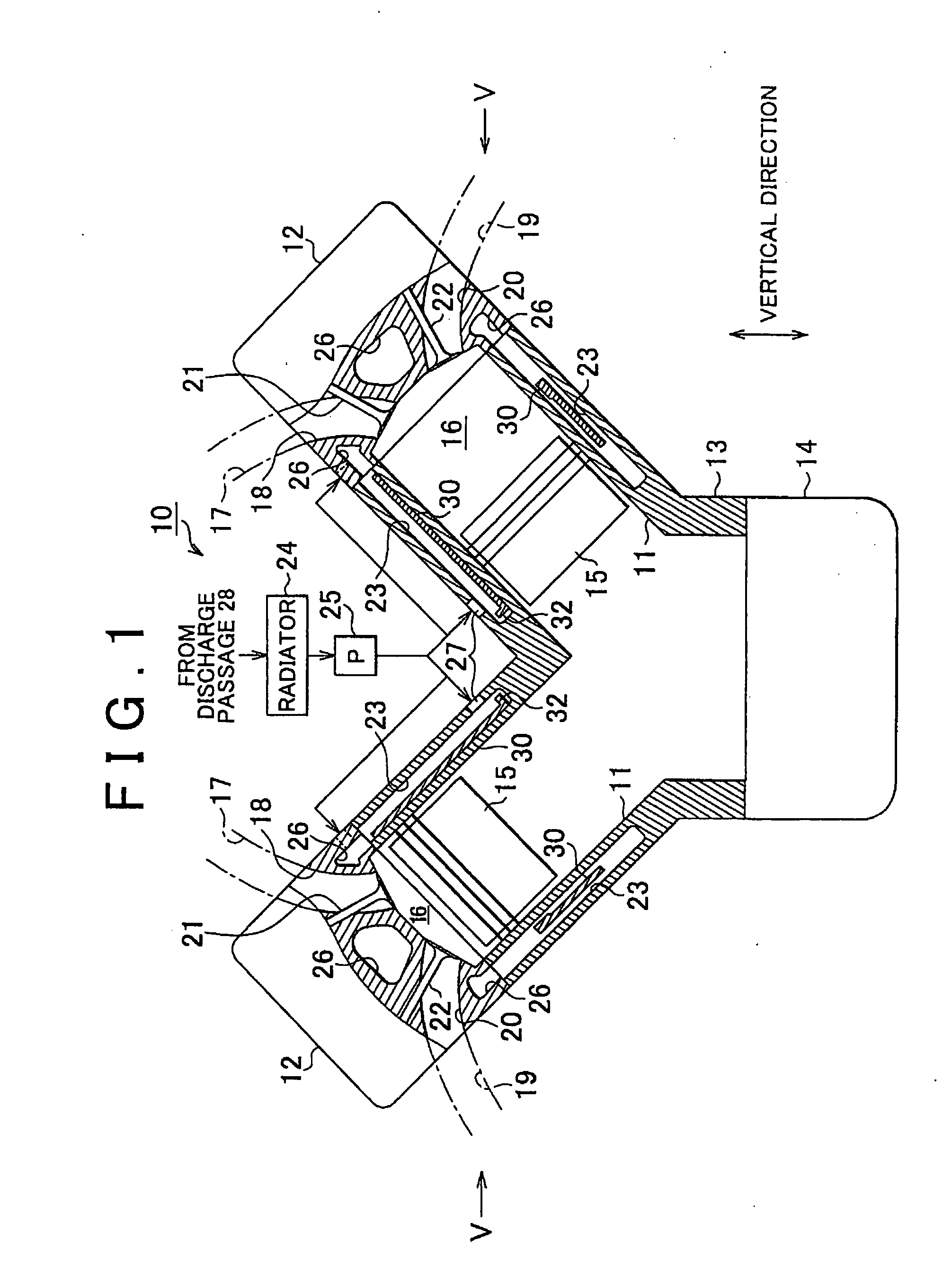
[0037]An embodiment of the invention will be described. FIG. 1 shows a schematic configuration of an internal combustion engine according to the embodiment. As shown in FIG. 1, the internal combustion engine 10 according to the embodiment includes two banks V. In each bank V, plural cylinder bores 11 are formed (four cylinder bores 11 are formed in the embodiment). The internal combustion engine 10 is a V-type internal combustion engine. The banks V are disposed in a V-formation such that a predetermined angle (90° in this embodiment) is formed between the two banks V.

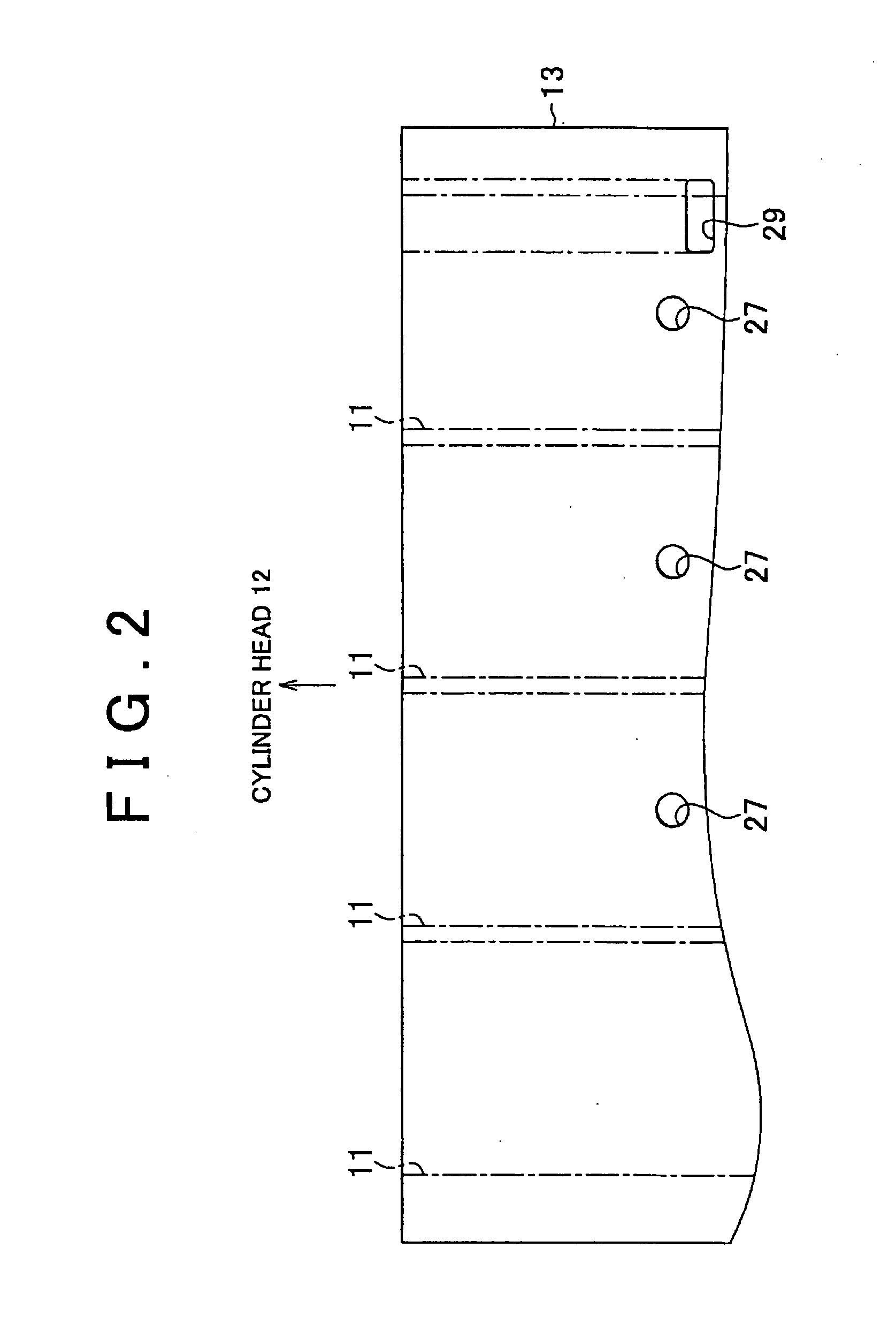
[0038]The internal combustion engine 10 includes a cylinder head 12, a cylinder block 13, and a lower case 14. The cylinder head 12 constitutes the upper portion of the banks V. The cylinder block 13 is formed by integrating the lower portion of the banks V with the upper portion of a crank case. A lower case 14 constitutes the lower portion of the crank case of the internal combustion engine 10.

[0039]In the cylinder b...


PUM


Abstract

In a cylinder block of an internal combustion engine, a water jacket in which coolant is circulated is formed around cylinder bores. In the cylinder block, an introduction passage, through which the coolant is introduced from the outside of the water jacket to the inside of the water jacket, is formed. A spacer, which extends along at least a portion of the periphery of the cylinder bores is provided in the water jacket. The spacer is disposed such that the inner wall surface of the spacer contacts the outer wall surfaces of the cylinder bores in an opening-side area of the cylinder block, where an opening of the introduction passage is formed, and the inner wall surface of the spacer does not contact the outer wall surfaces of the cylinder bores in an opposite opening-side area opposite to the opening-side area with respect to the cylinder bores.

Description

INCORPORATION BY REFERENCE[0001]The disclosure of Japanese Patent Application No. 2006-244520 filed on Sep. 8, 2006 including the specification, drawings and abstract is incorporated herein by reference in its entirety.BACKGROUND OF THE INVENTION[0002]1. Field of the Invention[0003]The invention relates to a cylinder block and an internal combustion engine where a spacer that defines a flow passage for coolant is provided in a water jacket.[0004]2. Description of the Related Art[0005]Generally, an internal combustion engine includes a cylinder block in which cylinder bores are formed. A water jacket, which surrounds the cylinder bores, is formed in the cylinder block. An introduction passage, which connects the inside and the outside of the water jacket, is formed in the cylinder block. Coolant is introduced into the water jacket through the introduction passage. The internal combustion engine is cooled through heat transfer from the wall surface of the water jacket to the coolant f...

Claims


Application Information

Patent Timeline
Patent Type & Authority Applications(United States)
IPC IPC(8): F02F1/14
CPCF02F1/14F01P3/02
Inventor NAKADA, TAKANORIHATANO, MAKOTO
Owner TOYOTA JIDOSHA KK
Why Eureka
Try Eureka