Honeycomb structure body

a technology of honeycomb and structure body, which is applied in the direction of domestic applications, machines/engines, and filtration of dispersed particles, can solve the problems of insufficient purification efficiency of exhaust gas in honeycomb structure body, and achieve the effect of reducing variation of exhaust gas purification performance, uniform flow speed of exhaust gas, and reducing the amount of flow

Inactive Publication Date: 2018-05-22
DENSO CORP
View PDF14 Cites 0 Cited by
  • Summary
  • Abstract
  • Description
  • Claims
  • Application Information

AI Technical Summary

Benefits of technology

[0009]The honeycomb structure body previously described has the cell density distribution in which a cell density is reduced continuously or stepwise in a radial direction from the center portion to the outer peripheral section. Accordingly, when a throttle opening is large and an overall flow amount of exhaust gas becomes large, it is possible to have a uniform flow speed of the exhaust gas in the inside of the honeycomb structure body. As a result, this makes it possible to reduce variation of exhaust gas purification performance of the honeycomb structure body through which a large amount of exhaust gas flows.
[0010]On the other hand, when a throttle opening is small and an overall flow amount of exhaust gas becomes small, a large amount of the exhaust gas flows in the section having a small cell density. In the structure of the honeycomb structure body, the wave shaped cell walls are arranged in the formation section having a small cell density, which satisfies the predetermined cell density ratio previously described, outside in the radial direction of the formation section at the center portion. Because the wave shaped cell walls have a large heat capacity, it is possible to suppress a temperature of the honeycomb structure body from decreasing even if a temperature of the exhaust gas decreases. From the point of view, this makes it possible to suppress a temperature of the honeycomb structure body from decreasing. In addition, it is possible to suppress decreasing the exhaust gas purification performance of the honeycomb structure body. Still further, the structure of the honeycomb structure body previously described makes it possible to reduce a temperature difference in the inside of the honeycomb structure body, and prevent generation of cracks in the honeycomb structure body by thermal stress.
[0011]In addition, the cell walls arranged in the formation section at the center portion, inside of the formation section of the wave shaped cell wall, are the flat shaped cell walls. This makes it possible to reduce increasing of a heat capacity of the honeycomb structure body as compared with a structure in which the wave shaped cell walls are arranged in the center portion. It is therefore possible to quickly increase a temperature of the honeycomb structure body, for example, immediately after an engine starts. From the viewpoint of this, it is possible to suppress the reduction of the exhaust gas purification performance. Further, because the honeycomb structure body has the flat shaped cell walls arranged in the formation section having a high cell density at the center portion, it is possible to suppress a pressure loss of the honeycomb structure body from increasing.
[0012]As previously described, the honeycomb structure body reduces the variation of the exhaust gas purification performance due to the drive condition. This makes it possible to reduce exhaust gas emission in all driving modes of a vehicle.

Problems solved by technology

As a result, the honeycomb structure body has an insufficient purification efficiency of exhaust gas.

Method used


Image

  • Honeycomb structure body
  • Honeycomb structure body
  • Honeycomb structure body

Examples


embodiments

First Exemplary Embodiment

[0032]Next, a description will now be given of a plurality of honeycomb structure bodies (sample E1 to sample E3) according to the first exemplary embodiment, and a plurality of honeycomb structure bodies (sample C1 to sample C3) as comparative samples with reference to figures. First, the honeycomb structure body 1 as the sample E1 will be explained.

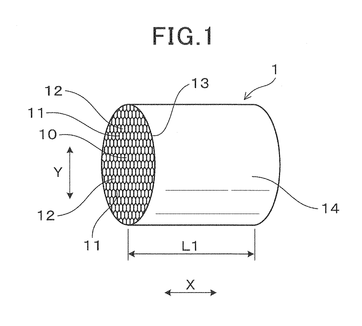
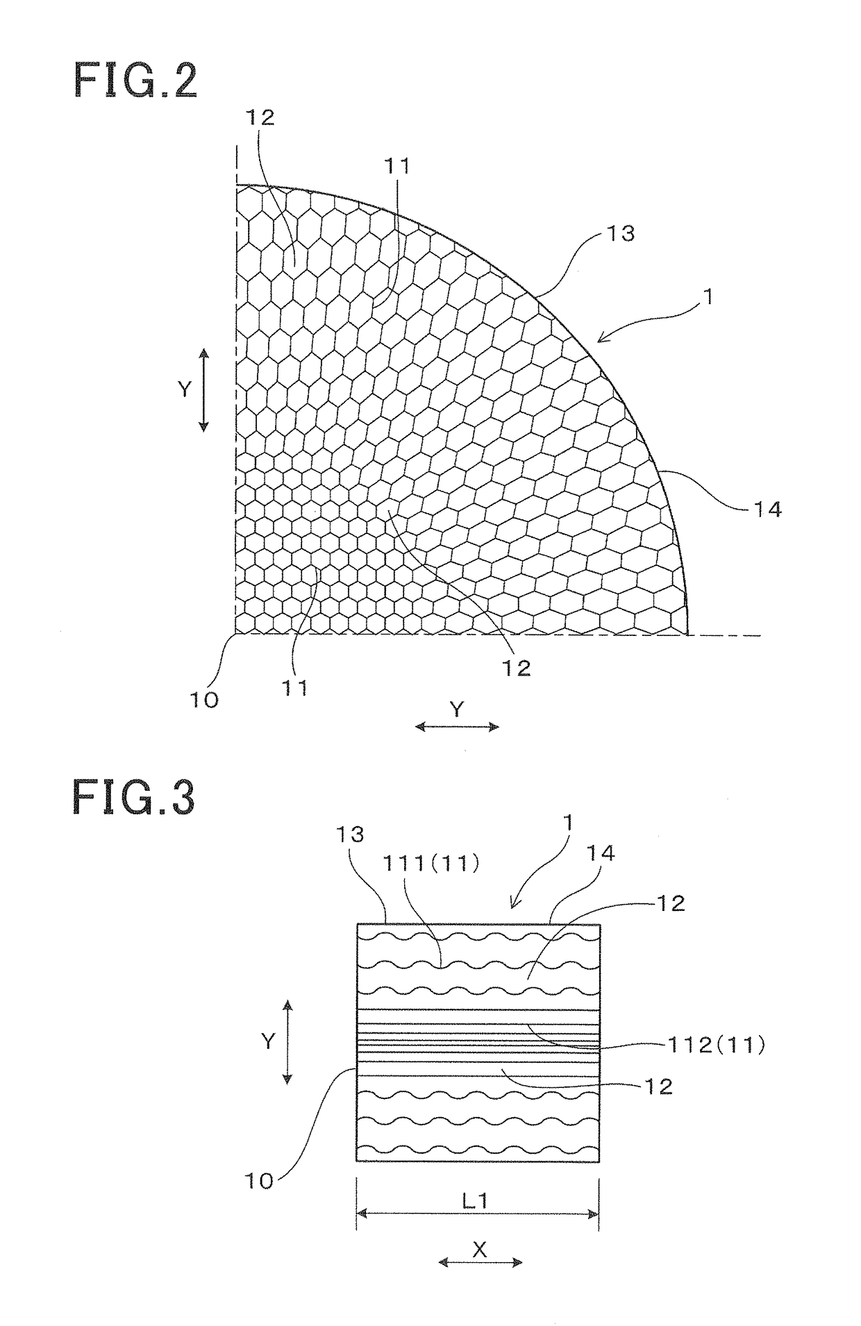
[0033]As shown in FIG. 1 and FIG. 2, the honeycomb structure body 1 as the sample E1 has cell walls 11 and a plurality of cells 12. The cell walls 11 are arranged in a lattice arrangement to form the cells 12 so that the cell 12 is surrounded by the cell walls 11. The honeycomb structure body 1 has a cell density distribution in which a cell density is reduced continuously or stepwise from the center portion 10 in a radial direction Y to an outer peripheral portion 13. As shown in FIG. 3, the honeycomb structure body 1 has wave shaped cell walls 111 extending in an axial direction X and flat shaped cell walls 1...

second exemplary embodiment

[0057]Next, a description will be given of the honeycomb structure body according to the second exemplary embodiment in which a cell density distribution which is different from that of the honeycomb structure body 1 according to the first exemplary embodiment. A description will now be given of the honeycomb structure body (the samples E4 to E6) according to the second exemplary embodiment and the honeycomb structure body (the sample C4 to C6) as the comparative samples.

[0058]As shown in FIG. 7, similar to the honeycomb structure body according to the first exemplary embodiment, the honeycomb structure body 1 (the samples E4 to E6) has a cell density which is reduced from the center portion 10 to the outer peripheral portion 13 in the radial direction Y. However, the second exemplary embodiment has a cell density which is different in change from the cell density of the first exemplary embodiment.

[0059]FIG. 8 shows a relationship between a distance (mm) measured from the center por...

first experiment

[0068]Next, a description will now be given of the evaluation of each of the honeycomb structure bodies (the samples E1 to E6) according to the first exemplary embodiment and the second exemplary embodiment previously described, and the evaluation of each of the honeycomb structure bodies (the samples C1 to C6) as the comparative samples. The evaluation contents are flow speed distribution, exhaust gas purification performance, pressure loss, and isostatic strength.

[0069]A description will now be given of the method of evaluating the flow speed distribution, the exhaust gas purification performance, the pressure loss and the isostatic strength.

[Evaluation of Flow Speed Distribution]

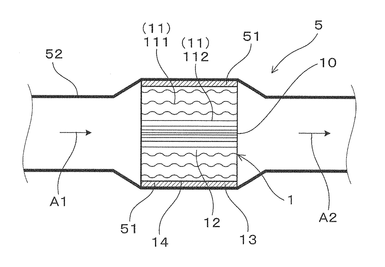
[0070]As shown in FIG. 9, a catalyst converter 8 was arranged in the inside of an exhaust gas pipe 52. The catalyst converter 8 was equipped with the honeycomb structure body 1 which was covered with aluminum sheet. The honeycomb structure body 1 supported catalyst therein in order to purifying exhaust ga...


PUM

PropertyMeasurementUnit
lengthaaaaaaaaaa
lengthaaaaaaaaaa
thicknessaaaaaaaaaa

Abstract

A honeycomb structure body has cell walls arranged in a lattice arrangement and a plurality of cells surrounded by the cell walls. The honeycomb structure body has a cell density distribution in which a cell density is reduced continuously or stepwise from a center portion to an outer peripheral portion in a radial direction. The honeycomb structure body has wave shaped cell walls and flat shaped cell walls which extend in an axial direction. Particularly, the wave shaped cell walls are formed in a formation section having a cell density ratio of not more than 0.85 to a maximum cell density. The region having the flat shaped cell walls is inside the region having the wave shaped cell walls.

Description

CROSS-REFERENCE TO RELATED APPLICATION[0001]This application is related to and claims priority from Japanese Patent Applications No. 2014-42955 filed on Mar. 5, 2014, and No. 2015-9331 filed on Jan. 21, 2015, the contents of which are hereby incorporated by reference.TECHNICAL FIELD[0002]The present invention relates to honeycomb structure bodies having a structure in which a cell density is reduced continuously or stepwise from a center portion to an outer peripheral portion in a radial direction of the honeycomb structure body.BACKGROUND ART[0003]There has been known a device having a honeycomb structure body arranged inside of an exhaust gas pipe, which is capable of purifying exhaust gas emitted from an internal combustion engine mounted on a motor vehicle, etc. In general, the honeycomb structure body has a plurality of cell walls and cells. The cell walls are arranged in a lattice arrangement. Each of the cells is formed by the cell walls. When a high temperature exhaust gas f...

Claims


Application Information

Patent Timeline
Patent Type & Authority Patents(United States)
IPC IPC(8): B01D46/24C04B35/195F01N3/28F01N3/022C04B38/00
CPCF01N3/0222B01D46/2474C04B35/195C04B38/0009C04B38/0074F01N3/2828B01D46/2429Y10T428/24149B01D2046/2433B01D2046/2437C04B2235/3218C04B2235/349C04B2235/3418C04B2235/3445C04B2235/5296F01N2330/06F01N2330/48F01N2330/60C04B38/0006C04B2111/00793C04B2111/0081B01D46/24492B01D46/24491B01D46/2484B01D46/2482C04B38/0051C04B38/0054B01D46/247B01D46/2486
Inventor TAMAI, KOJI
Owner DENSO CORP
Why Eureka
Try Eureka