Exhaust muffler capable of automatically adjusting overflow area

A technology of exhaust muffler and flow area, which is applied in the direction of exhaust devices, noise reduction devices, engine components, etc. It can solve the problems of unable to adjust the cross-sectional area of ​​air flow and complex structure, so as to improve the noise reduction effect and reduce the exhaust back Pressure, reduce the effect of air regeneration noise

Inactive Publication Date: 2010-08-25
CHONGQING UNIV
View PDF5 Cites 16 Cited by
  • Summary
  • Abstract
  • Description
  • Claims
  • Application Information

AI Technical Summary

Problems solved by technology

However, the main problem of this device is that the structure is relatively complicated, and the cross-sectional area of ​​the air flow cannot be adjusted, and the noise problem of the muffler under the condition of large exhaust flow rate cannot be fundamentally solved.

Method used


Image

  • Exhaust muffler capable of automatically adjusting overflow area
  • Exhaust muffler capable of automatically adjusting overflow area
  • Exhaust muffler capable of automatically adjusting overflow area

Examples


Embodiment 1

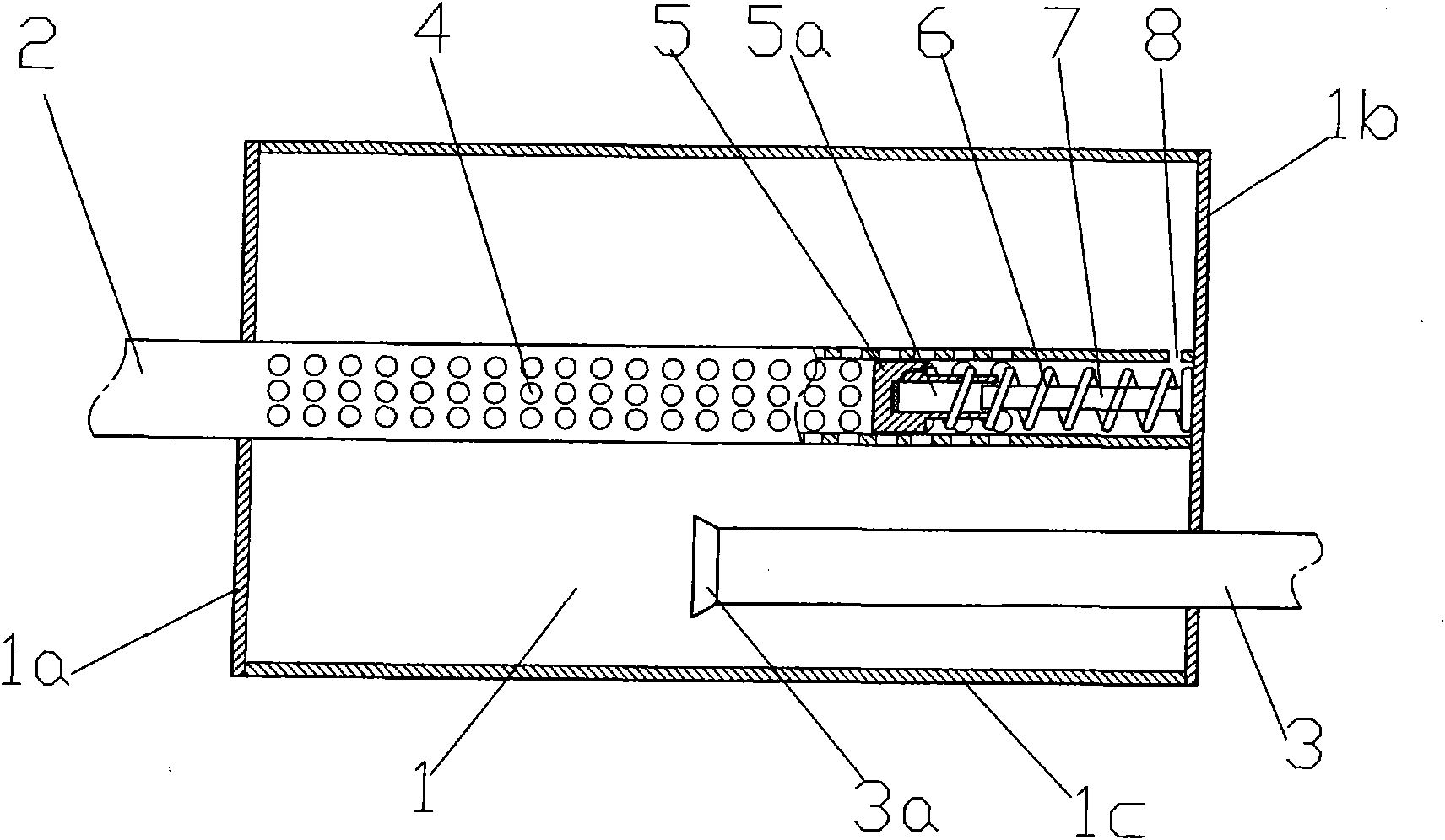
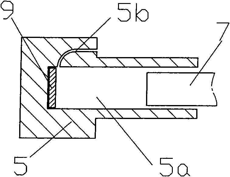
[0023] Fig. 1 is a structural schematic diagram of the first embodiment of the present invention, Fig. 2 is an enlarged view of the cooperation structure of the piston and the guide rod, and Fig. 3 is an enlarged view of the cooperation of the piston and the guide rod with a smooth transition arc surface end face, as shown in the figure: this embodiment The exhaust muffler with automatic adjustment of the flow area includes the muffler intake pipe 2, the expansion chamber 1 and the muffler exhaust pipe 3. The muffler intake pipe 2 is connected to the exhaust port of the engine through the air inlet, The air port is connected to the expansion chamber 1, and the muffler exhaust pipe 3 is connected to the expansion chamber 1 through the air inlet 3a. Through hole 4, the muffler inlet pipe 2 is provided with a piston 5 that can reciprocate and slide along the inner wall of the tube on the inner circle of the pipe section of the radial through hole 4. The front end of the piston 5 f...

Embodiment 2

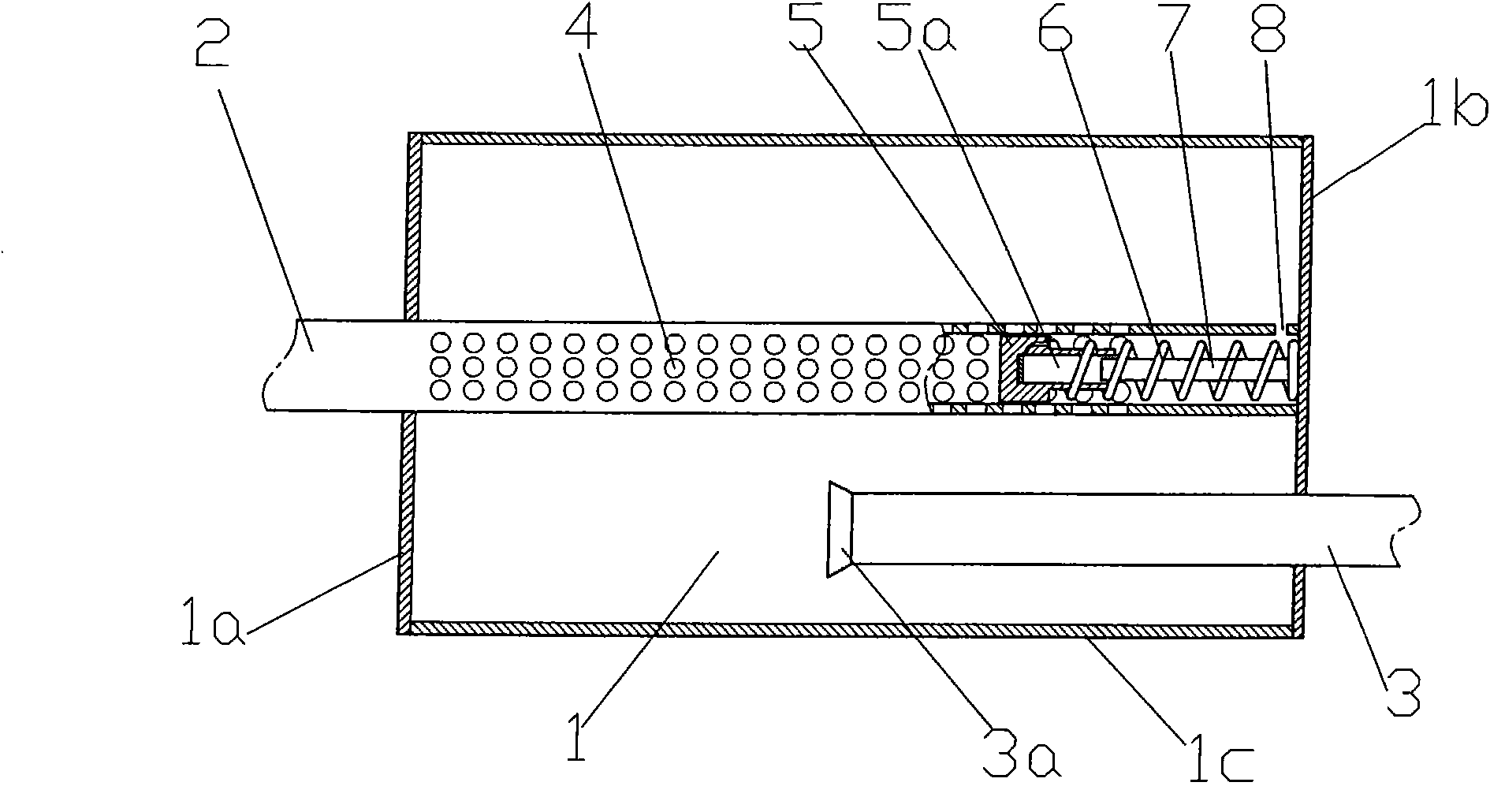
[0035] Fig. 4 is a schematic structural diagram of the second embodiment of the present invention. As shown in the figure, the difference between the present embodiment and the first embodiment is only that a rear end cover of the inlet pipe 2 of the muffler and the rear end cover of the expansion chamber 1 is provided. Set distance and seal through end cap 10 instead of directly sealing through rear end cap 1b of expansion chamber 1; this structure makes full use of the volume of expansion chamber 1 and eliminates exhaust noise to the greatest extent.


PUM


Abstract

The invention discloses an exhaust muffler capable of automatically adjusting the overflow area, which comprises an air inlet pipe, an expansion chamber and an air outlet pipe, wherein the inner circle of the section (provided with radial through-holes) of the air inlet pipe is provided with a piston which can slide to and fro along the inner wall of the pipe, and the front end of the piston faces the air inlet direction, while the rear end is provided with a pressure spring which can apply pressure (with a direction opposite to the air inlet direction) to the rear end. The invention adopts a structure that the exhaust pipe section of the air inlet pipe is provided with the piston which divides the exhaust pipe section into an exhaust part and a closed part, the position of the piston can be automatically adjusted according to the exhaust pressure and the piston can reset under the action of the spring when the exhaust pressure is low; therefore, the exhaust muffler has the advantages of adjusting the area of the airflow ventilating section according to the exhaust gas flow of an engine under different working conditions, keeping the exhaust airflow in an even flow velocity, effectively lowering the exhaust backpressure, reducing the regenerated noise of the airflow, improving the erasure effect of the muffler, and having a positive significance for reducing the fuel consumption and carbon dioxide emission of an automobile.

Description

technical field [0001] The invention relates to an accessory part of an automobile, in particular to an exhaust muffler which can automatically adjust the flow area. Background technique [0002] Traffic noise is the noise generated during the driving of motor vehicles, and it is the main noise source in urban environmental noise; while automobile exhaust noise is the main noise source of automobile noise, and it is also the focus of urban environmental noise control. [0003] In order to reduce exhaust noise, motor vehicles generally use exhaust mufflers to exhaust, and mufflers are also the most effective noise reduction means commonly used to control exhaust noise. In the prior art, the silencing performance of basically all engine exhaust mufflers depends on fixed structural parameters, and the silencing frequency cannot be automatically adjusted with changes in engine operating conditions, and is always in a passive state; while the exhaust flow of the engine varies wit...

Claims


Application Information

Patent Timeline
Patent Type & Authority Applications(China)
IPC IPC(8): F01N1/00F01N13/00
Inventor 李沛然邓兆祥向飞
Owner CHONGQING UNIV
Why Eureka
Try Eureka