Cooling device, cooling system and experimental system and method of cooling device

A heat dissipation device and pressure chamber technology, applied in the direction of measuring devices, machine/structural component testing, instruments, etc., can solve the problems of uneven heat dissipation, poor heat dissipation efficiency, easy corrosion, etc., and achieve large contact area, good heat dissipation effect, Strong anti-corrosion effect

Inactive Publication Date: 2017-11-07
UNIV OF ELECTRONICS SCI & TECH OF CHINA
View PDF10 Cites 16 Cited by
  • Summary
  • Abstract
  • Description
  • Claims
  • Application Information

AI Technical Summary

Problems solved by technology

[0008] Based on the above technical problems, the present invention provides a heat dissipation device, thereby solving the technical problems of poor heat dissipation efficiency, uneven heat dissipation and easy corrosion of previous heat dissipation devices; at the same time, based on the heat dissipation device, the present invention also discloses a Heat dissipation system composed of heat dissipation device, experimental system and method of heat dissipation device

Method used


Image

  • Cooling device, cooling system and experimental system and method of cooling device
  • Cooling device, cooling system and experimental system and method of cooling device
  • Cooling device, cooling system and experimental system and method of cooling device

Examples


Embodiment 1

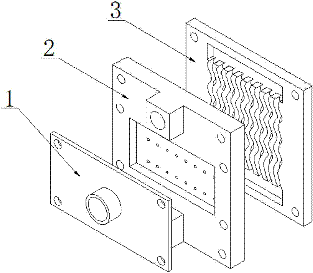
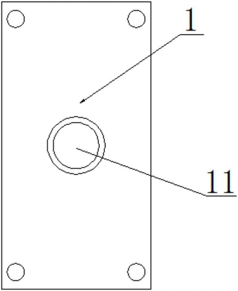
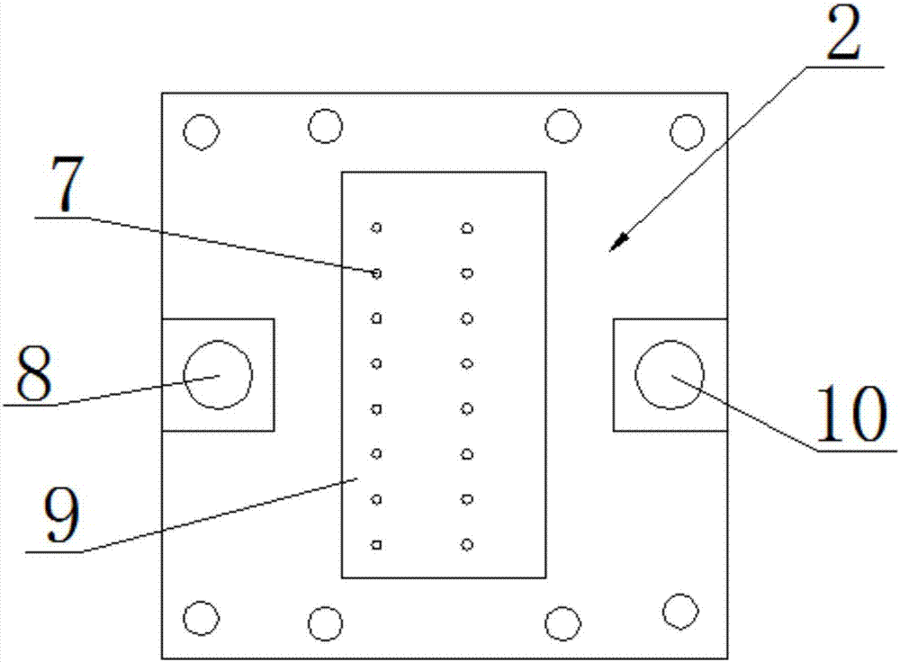
[0049] Such as Figure 1-7 As shown, a heat dissipation device includes a pressure chamber cover 1, a perforated plate 2, and a micro-channel base plate 3 that are sequentially sealed and connected by waterproof silicone grease; the side of the micro-channel base plate 3 connected to the perforated plate 2 is symmetrically opened There are a first liquid collection chamber 4 and a second liquid collection chamber 6, and the first liquid collection chamber 4 and the second liquid collection chamber 6 communicate through several tiny channels 5; the perforated plate 2 is connected to the pressure chamber cover 1 One side is concave to form a cavity 9, and the cavity 9 is sealed by the pressure chamber cover 1 to form a pressure chamber; the bottom of the pressure chamber runs through a plurality of jet holes 7 corresponding to and communicating with the micro channels 5; the perforated plate 2 is located at Both sides of the cavity are also provided with a first liquid outlet 8 ...

Embodiment 2

[0055] In this embodiment, on the basis of the technical solution in Embodiment 1, the micro-channel structure is optimized, specifically: the side walls of the micro-channel 5 are arranged in a sinusoidal or cosine curve to form a wave-wall microchannel.

[0056] The microchannel of this embodiment is a wave-wall microchannel, and the surface shape of the wave-wall microchannel adopts a new microchannel heat dissipation structure of a sine curve or a cosine curve. Compared with other microchannel heat dissipation structures, not only the contact area is large, but the flow rate of the flow channel Uniform, faster flow rate, less pressure loss, can maximize the use of heat dissipation performance.

Embodiment 3

[0058] In this embodiment, on the basis of the technical solution of embodiment 1 or embodiment 2, the following optimization is made: each of the micro channels 5 is connected with at least two jet holes 7 .

[0059] In this embodiment, each tiny channel 5 is connected with a plurality of jet holes 7, that is to say, each jet field affects each other as mentioned above, thereby affecting the overall flow and heat transfer, improving the heat transfer effect and efficiency.

[0060] Preferably, each of the tiny channels 5 is connected with two jet holes 7 .


PUM


Abstract

The invention relates to a cooling device which comprises a pressure cavity cover piece, a perforation plate and a microchannel matrix plate in sequential sealed connection through waterproof silica gel. A first liquid collection cavity and a second liquid collection cavity are symmetrically formed on one side, connected with the perforation plate, of the microchannel matrix plate and communicated through a plurality of microchannels, and one side, connected with the pressure cavity cover piece, of the perforation plate inwards concaves to form a cavity which is sealed through the pressure cavity cover piece to form a pressure cavity; multiple perforation holes communicated with the microchannels penetrate the bottom of the pressure cavity, the perforation plate is provided with a first liquid outlet and a second liquid outlet on two sides of the cavity, and a liquid inlet communicated with the pressure cavity is formed in the middle of the pressure cavity cover piece. Cooling is realized by means of combining jet flow impact with the microchannels, so that the characteristic that the microchannels are large in heat exchange area can be utilized, the characteristic that jet flow impact is high in local heat exchange efficiency can be utilized, the problem of nonuniform cooling is solved, and heat exchange efficiency of the whole device is improved.

Description

technical field [0001] The invention relates to a heat dissipation device, which belongs to the technical field of heat dissipation of electronic equipment, and also discloses a heat dissipation system composed of the heat dissipation device, an experimental system and a method of the heat dissipation device. Background technique [0002] With the rapid development of electronic science and technology, the power density of electronic equipment is gradually increasing. With the vigorous development of the computer field, the demand for computing performance is increasing day by day, and the frequency of the processor is also getting higher and higher. Coupled with the rise of concepts such as big data and cloud computing, the processing capability of computer chips is required to continue to increase. The problem is that the heat generated by the central processing unit (CPU) is also increasing, so the performance requirements of the radiator are getting higher and higher. A...

Claims


Application Information

Patent Timeline
Patent Type & Authority Applications(China)
IPC IPC(8): G06F1/20G01M99/00
Inventor 徐尚龙郑书勤姚晟丰瑞鑫罗冲罗欣李垚莹徐冲
Owner UNIV OF ELECTRONICS SCI & TECH OF CHINA
Why Eureka
Try Eureka