Multi-stage denoiser and valve with same

A technology of noise reducer and noise reduction cover, applied in the field of noise reduction, can solve the problems of affecting the normal flow rate of fluid in the pipeline, low noise reduction effect of the noise reduction device, etc. Effect

Active Publication Date: 2015-09-16
NEWAY VALVE SUZHOU
View PDF6 Cites 17 Cited by
  • Summary
  • Abstract
  • Description
  • Claims
  • Application Information

AI Technical Summary

Problems solved by technology

[0007] Therefore, the technical problem to be solved by the present invention is to overcome the technical problem that the noise reduction effect of the noise reduction device in the prior art is low and the normal flow velocity of the fluid in the pipeline is seriously affected by the turbine, thereby providing a noise reduction device with high noise reduction effect and no noise. Noise reduction device that affects the normal flow rate of fluid in the pipeline due to the turbine

Method used


Image

  • Multi-stage denoiser and valve with same
  • Multi-stage denoiser and valve with same
  • Multi-stage denoiser and valve with same

Examples


Embodiment 1

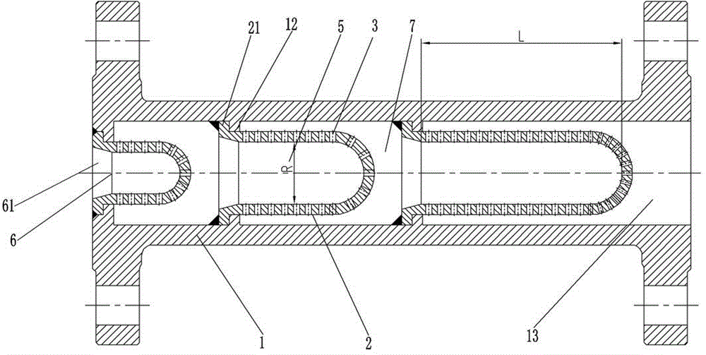
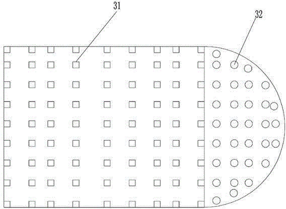
[0039] This embodiment provides a multi-stage noise reducer, such as figure 1 As shown, it includes a hollow noise reduction cylinder 1, and a three-stage noise reduction cover 2, which is arranged in the hollow noise reduction cylinder 1 along the extension direction of the hollow noise reduction cylinder 1, and each stage of the noise reduction cover 2 has The fluid cavity 5 and the fluid inlet 6 arranged at the head of the fluid cavity 5 are provided with a plurality of through holes 3 on the wall of the fluid cavity 5 of the noise reduction cover 2 of each stage, and the fluid cavity of the next stage noise reduction cover 2 The fluid inlet 6 of 5 is set corresponding to the tail of the noise reduction cover 2 of the previous stage, and forms a buffer cavity 7 with the tail of the noise reduction cover 2 of the previous stage.

[0040] For the above-mentioned three-stage noise reducer, a three-stage noise reduction cover 2 is set in the hollow noise reduction cylinder 1, a...

Embodiment 2

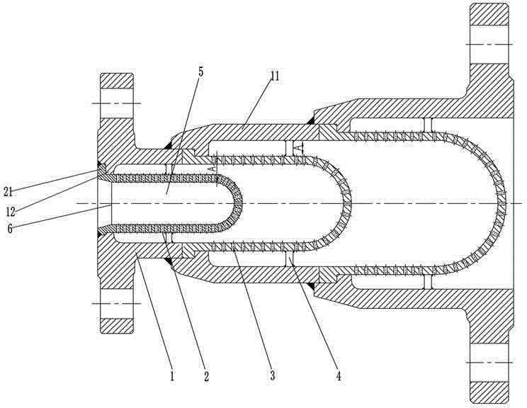
[0055] This embodiment provides a multi-stage noise reducer, such as image 3 As shown, the main difference from Embodiment 1 is that the hollow noise reduction cylinder 1 includes at least three stages of noise reduction sections 11 whose radial diameter gradually increases along the axial direction, and a noise reduction section 11 is installed in each stage of the noise reduction section 11. Among the multiple buffer cavities 7 formed by two adjacent noise reduction covers 2, the entrance width A of the buffer cavity 7 of the latter stage is larger than the entrance width A of the buffer chamber 7 of the previous stage.

[0056] By designing the hollow noise reduction cylinder 1 as three stages of noise reduction sections 11 with gradually increasing radial diameter along the axial direction, and setting a primary noise reduction cover 2 in each stage of noise reduction section 11, it is convenient to use this multiple The stage noise reducer is applied to the situation whe...

Embodiment 3

[0059] This embodiment provides a valve, including a valve body 8 and a fluid outflow channel 81, the outlet of the outflow channel (81) is fixedly connected with a noise reducer along the axial direction, and the noise reducer is the above-mentioned embodiment 1 or implementation The noise reducer in Example 2, and the valves in this embodiment can be eccentric rotary control valves, V-shaped control ball valves, butterfly valves, and other valves that require noise reduction.

[0060] For example, the three-stage noise reducer in which the hollow noise reduction cylinder 1 in Embodiment 1 is a straight cylinder is applied to a straight-stroke valve, such as a single-seat regulating valve, and the inlet end of the hollow noise reduction cylinder 1 of the noise reducer is connected to the single-seat control valve. The outflow channel 81 of the fluid behind the spool of the seat regulating valve is fixedly connected, and its assembly drawing is used, such as Figure 5 shown. ...


PUM


Abstract

The invention discloses a multi-stage denoiser and a valve with the same. The multi-stage denoiser comprises a hollow denoising cylinder and at least two stages of denoising covers. The denoising covers are arranged in the hollow denoising cylinder in the extension direction of the hollow denoising cylinder. Each stage of denoising cover is provided with a fluid cavity and a fluid inlet formed in the head portion of the fluid cavity. The wall of the fluid cavity of each stage of denoising cover is provided with a plurality of through holes. The fluid inlet of the fluid cavity of the rear stage of denoising cover corresponds to the tail portion of the front stage of denoising cover and forms a buffer cavity together with the tail portion of the front stage of denoising cover. The valve comprises a valve body and an outflow passageway of fluid. The outlet of the outflow passageway is fixedly connected with the denoiser in the axial direction. By arranging the multiple stages of denoising covers, the denoising efficiency is improved, the denoising effect is achieved through the frequency shift effect of small hole spraying, and the fluid flow speed is uniform through the buffer cavity. The vibration caused by fluid impact to the denoiser is reduced in the medium flowing process, and therefore the stability of the product is improved, and the overall service life of the denoiser is prolonged.

Description

technical field [0001] The invention relates to the technical field of noise reduction, in particular to a multistage noise reducer and a valve with the noise reducer. Background technique [0002] Valves are the control components in the fluid delivery system. They have the functions of cut-off, adjustment, flow diversion, prevention of reverse flow, pressure stabilization, flow diversion or overflow pressure relief, etc., and can be widely used in delivery devices for compressible or incompressible media. When the compressible medium passes through the valve, noise will be generated due to throttling, especially for regulating valves with higher throttling requirements, noise has become one of the main indicators for users to measure the quality of valve products. [0003] In order to meet the customer's requirement for the noise generated by valve products to be as low as possible, various manufacturers at home and abroad have also developed a series of noise reduction st...

Claims


Application Information

Patent Timeline
Patent Type & Authority Applications(China)
IPC IPC(8): F16L55/033F16K47/02
CPCF16K47/02F16L55/033
Inventor 何庆伟
Owner NEWAY VALVE SUZHOU
Why Eureka
Try Eureka