Sensor device having non-contact charge function and containers having the same

a sensor and non-contact technology, applied in the direction of independent non-interacting antenna combinations, differential interacting antenna combinations, instruments, etc., can solve the problems of high charge sensitive of the antenna, the ic tag of the sensor, the mounting of the sensor, etc., and achieve significant antenna gain and improve the charge function

Active Publication Date: 2008-03-13
SEMICON ENERGY LAB CO LTD
View PDF5 Cites 128 Cited by
  • Summary
  • Abstract
  • Description
  • Claims
  • Application Information

AI Technical Summary

Benefits of technology

[0012]In the sensor device having the foregoing structure, the antenna and the sensor portion are provided over different bases so that the different bases can perform transmission and reception of electric power and signals to each other using electromagnetic-coupled antennas. By separating a base receiving electromagnetic waves from a base provided with the sensor portion, miniaturization of the sensor portion can be achieved while the charge function can be improved.
[0013]According to the present invention, provision of the antenna receiving electromagnetic waves and the sensor potion over the different bases ...

Problems solved by technology

However, if a battery is charged by receiving radio waves for electric power, the size of an antenna needs to be larger, thereby making the antenna highly sensitive for sufficient charge.
As a result, an IC tag with the sensor, which is...

Method used


Image

  • Sensor device having non-contact charge function and containers having the same
  • Sensor device having non-contact charge function and containers having the same
  • Sensor device having non-contact charge function and containers having the same

Examples


embodiment mode 1

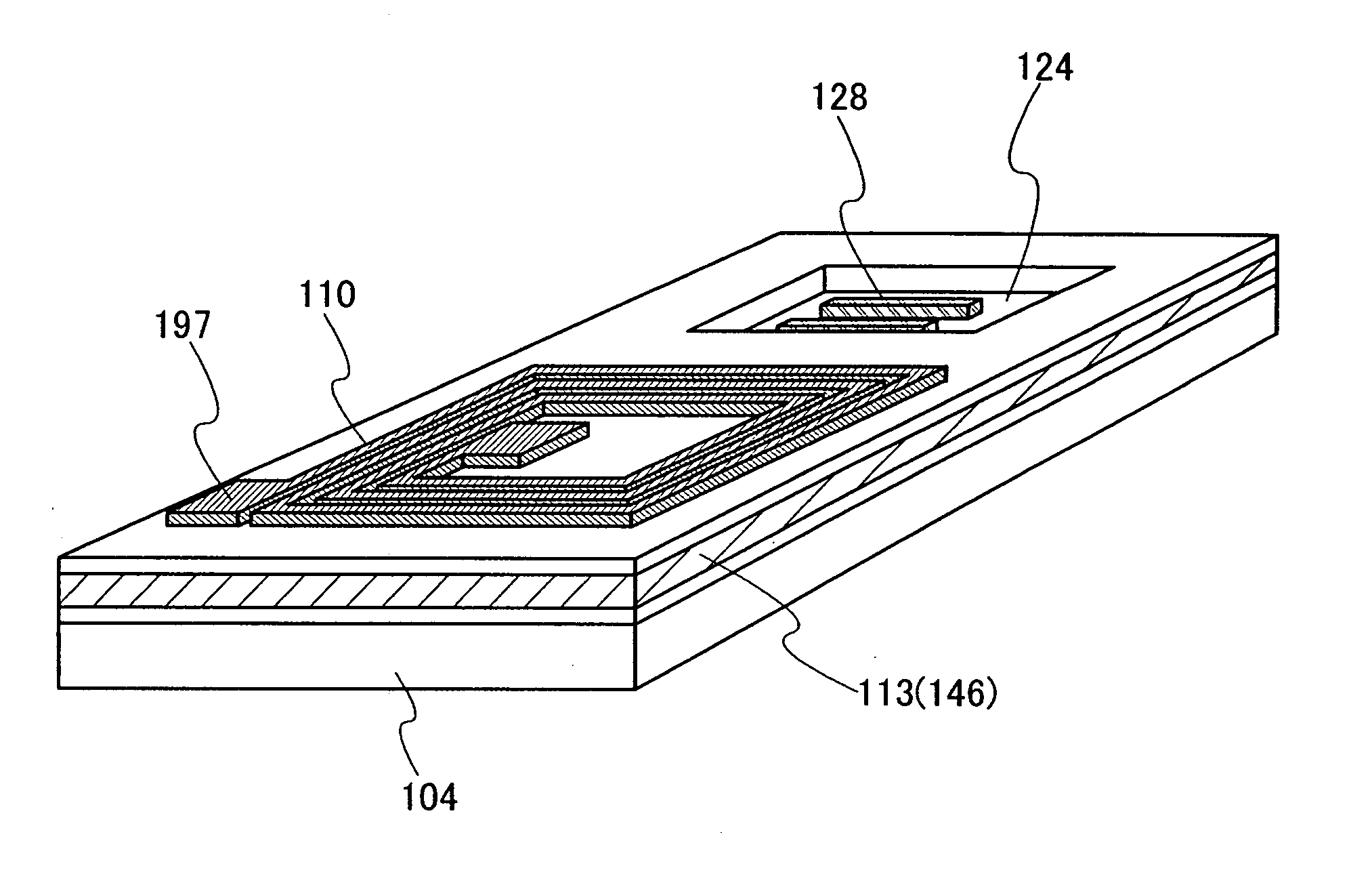
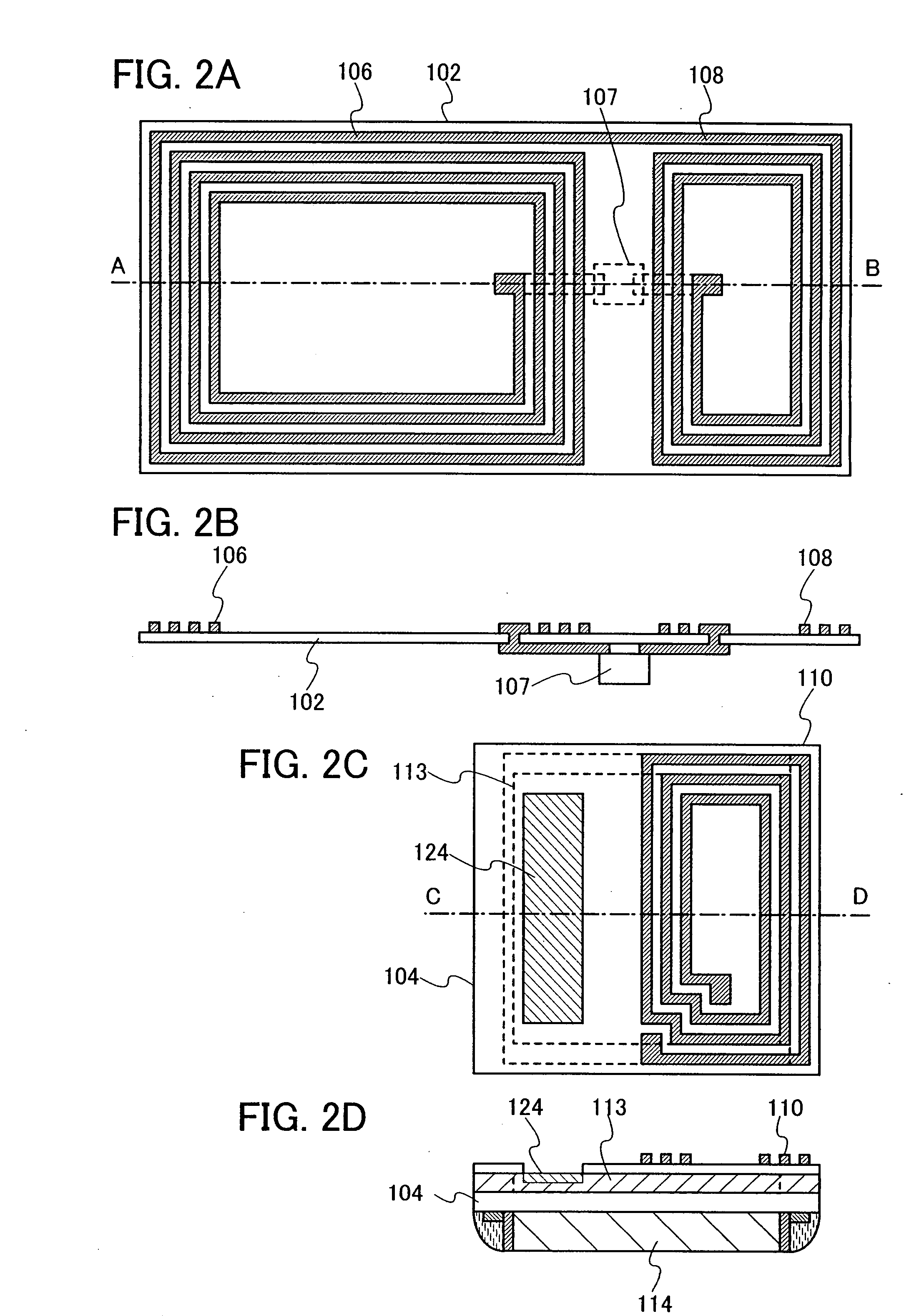
[0037]This embodiment mode will describe a structure in which an antenna for receiving electromagnetic waves and a sensor portion are provided on different bases in order to miniaturize the sensor device having a non-contact charge function with reference to drawings. In addition, this embodiment mode will describe a structure of the sensor device in which a first antenna for receiving electromagnetic waves is formed over a first base, and a CPU, a sensor portion, and a power storage portion for supplying electric power thereto are provided over a second base.

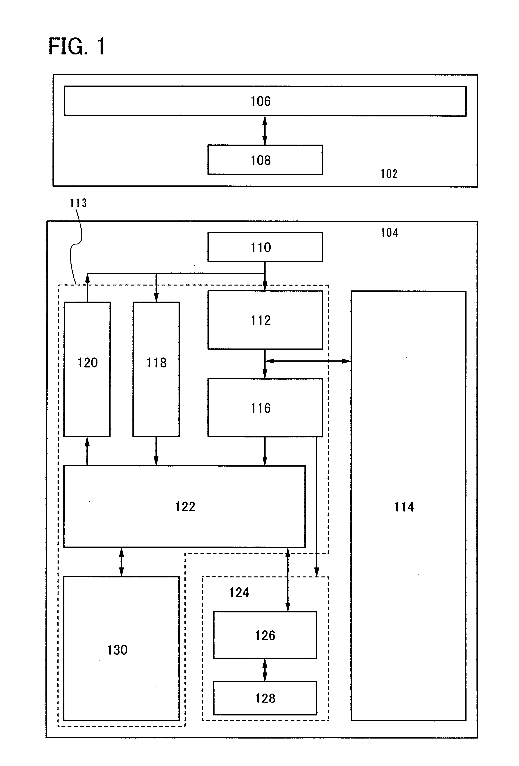
[0038]FIG. 1 is a block diagram showing a structure of the sensor device in accordance with this embodiment mode. This sensor device is composed of a first base 102 and a second base 104, which is separated from the first base 102. A first antenna 106 receiving electromagnetic waves is provided to the first base 102. The first antenna 106 constantly receives electromagnetic waves of from a submillimeter-wave band to a very long...

embodiment mode 2

[0055]This embodiment mode will describe another structure in which an antenna receiving electromagnetic waves and a sensor portion are provided with different bases so that a sensor device having a non-contact charge function can be miniaturized as in Embodiment Mode 1. In this embodiment mode, the sensor device, in which a first antenna receiving electromagnetic waves, a CPU, and a power storage portion are formed over a first base, and a sensor portion is provided over a second base, will be described.

[0056]FIG. 4 is a block diagram showing a structure of the sensor device in accordance with this embodiment mode. This sensor device is composed of a first base 102 and a second base 104. The first base 102 and the second base 104 are separate bases. The first base 102 has a power storage portion 114 and a circuit portion 144 of the first base. The second base 104 has a circuit portion 146 of the second base and a sensor portion 124.

[0057]A first antenna 131 receiving electromagneti...

embodiment mode 3

[0068]This embodiment mode will describe an example of a first base 102 that has a different mode from Embodiment Mode 2 with reference to FIG. 7 and FIG. 8. This embodiment mode shows an example of a sensor device having plural antennas to receive wide bands of electromagnetic waves and store electric power.

[0069]In a first base 102 described in FIG. 7, a circuit portion 144 of the first base includes components such as a rectification circuit 112, a constant-voltage circuit 116, an oscillation circuit 117, a demodulation circuit 118, a modulation circuit 120, a CPU 122, and a memory portion 130. A structure of the circuit portion 144 has functions similar to those in FIG. 4.

[0070]A first antenna 131 is used for transmission / reception of control commands or communication data, to / from an external device. A demodulation circuit 148 and a modulation circuit 150, which are connected to the first antenna 131 are circuits performing modulation / demodulation of control demands or communic...


PUM


Abstract

A first base having a first antenna receiving electromagnetic waves and a second base having a sensor portion are separated. An antenna is provided over each of the first base and the second base such that the antennas are electromagnetically coupled. The first antenna constantly receives electromagnetic waves to generate electromotive force and charges a power storage portion. Since the electric power of the power storage portion is also used for driving of a sensor portion, the sensor portion operates even without communication with the external device. Provision of the first antenna receiving electromagnetic waves and the sensor portion on different bases permits miniaturization of a base having the sensor portion. Further, provision of the power storage portion storing electric power converted from electromagnetic waves received by the antenna enables operating the sensor actively.

Description

BACKGROUND OF THE INVENTION[0001]1. Field of the Invention[0002]The present invention relates to a sensor device, which performs communication of data and supply / reception of drive electric power without contact, and containers having the same.[0003]2. Description of the Related Art[0004]Most of the products commercially available such as foods, medicines, and materials of the same are preserved in airtight containers to maintain safety, hygiene, and quality thereof. For example, some fresh foods or soft drinks are transported by vehicles in which the temperature of trunks can be controlled so that freshness can be preserved. Some medicines or foods lose their value as products once containers in which products are preserved are opened. That is, there is a case where confidence in the products' safety may be diminished.[0005]However, there is a problem in that consumers purchasing goods at the retail stage cannot know accurately how the products have been managed in the distribution...

Claims


Application Information

Patent Timeline
IPC IPC(8): H01Q7/00H01Q1/12H01Q21/00B65D23/12G06K19/07
CPCH01Q1/2208H01Q21/29H01Q21/28H01Q7/00H02J50/12
Inventor ARAI, YASUYUKI
Owner SEMICON ENERGY LAB CO LTD
Why Eureka
Try Eureka