Flat display and timing controller thereof

a timing controller and display technology, applied in the field of flat display, can solve the problems of reducing the display quality of the lcd panel, the discharge speed of the pixel electrode in the tft lcd is too slow, and the charge cannot be quickly released

Inactive Publication Date: 2008-03-13
HIMAX TECH LTD
View PDF14 Cites 22 Cited by
  • Summary
  • Abstract
  • Description
  • Claims
  • Application Information

AI Technical Summary

Benefits of technology

[0009]The invention is directed to a flat display, and more particularly to a flat display and a timing controller thereof for eliminating a residual image of the flat display by way of timing control when the flat display is shut down.

Problems solved by technology

This phenomenon cannot satisfy the visual exception of the user and decreases the display quality of the LCD panel after a long period of time has elapsed.
Taking a thin film transistor (TFT) LCD as an example, one of the main reasons for causing the shutdown residual image is that the discharge speed of the pixel electrode in the TFT LCD is too slow so that the charges cannot be quickly released and are remained in the liquid crystal capacitor after shutdown.
Thus, the charges cannot be completely discharged after a period of time has elapsed.
In the actual circuit implementation, however, adding the reset circuit 14 and the scan-row-fully-open pin XAO increases the number of the circuit components, the area of the printed circuit board and the package area, and thus the cost greatly increases.

Method used


Image

  • Flat display and timing controller thereof
  • Flat display and timing controller thereof
  • Flat display and timing controller thereof

Examples


first embodiment

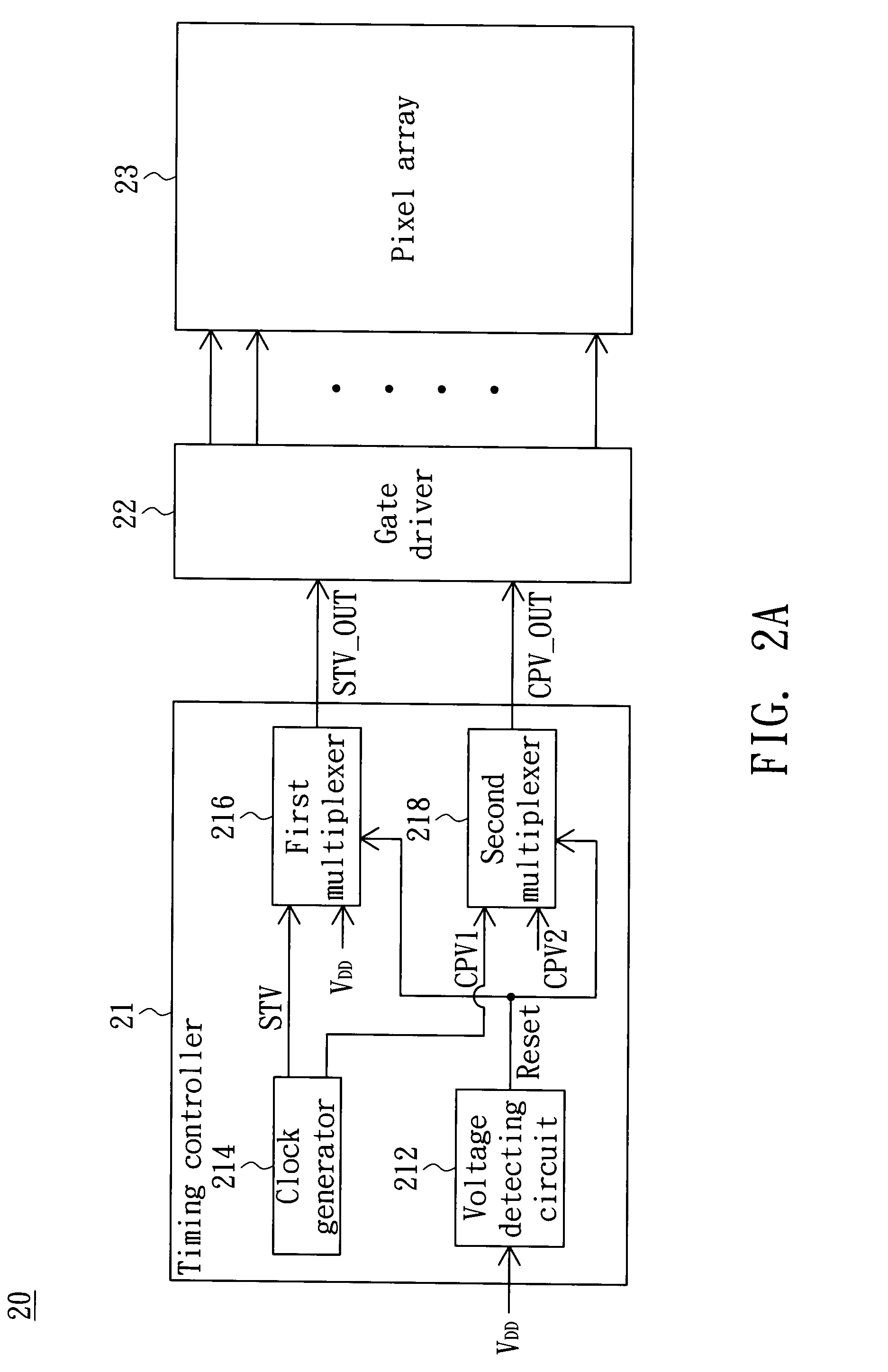
[0018]FIG. 2A is a block diagram showing a flat display 20 according to a first embodiment of the invention. Referring to FIG. 2A, the flat display 20, such as a LCD, includes a timing controller 21, a gate driver 22, a source driver (not shown in FIG. 2A) and a pixel array 23. The timing controller 21 includes a voltage detecting circuit 212, a clock generator 214, a first multiplexer 216 and a second multiplexer 218. The voltage detecting circuit 212 detects a variation of an operating voltage VDD and thus outputs a reset signal Reset. The clock generator 214 outputs a start signal STV and a first clock signal CPV1, which are required to make the gate driver 22 operate normally. The first multiplexer 216 is controlled by the reset signal Reset to select the start signal STV or a constant voltage as an output signal STV_OUT, wherein the constant voltage and the start signal STV have opposite levels. For example, when the start signal STV for the normal operation is the low level vo...

second embodiment

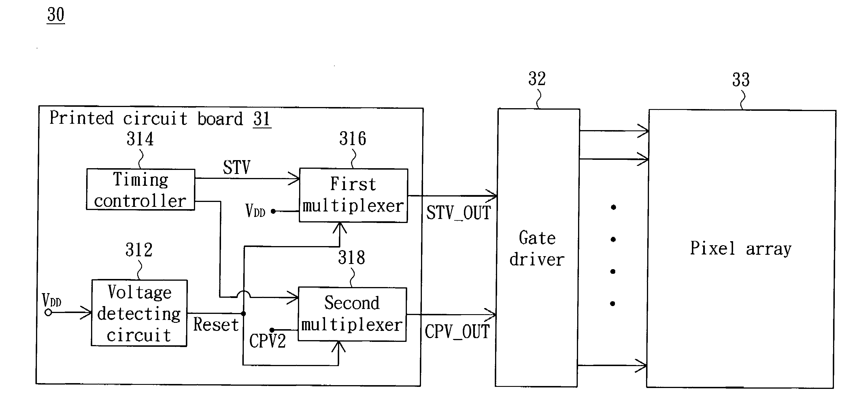
[0023]FIG. 3 is a block diagram showing a flat display 30 according to a second embodiment of the invention. Referring to FIG. 3, the flat display 30, such as a LCD, includes a gate driver 32, a source driver (not shown in FIG. 3), a pixel array 33, a voltage detecting circuit 312, a timing controller 314, a first multiplexer 316 and a second multiplexer 318. The voltage detecting circuit 312, the timing controller 314, the first multiplexer 316 and the second multiplexer 318 may be disposed on a printed circuit board 31. The voltage detecting circuit 312 detects a variation of an operating voltage VDD and thus outputs a reset signal Reset. The timing controller 314 outputs a start signal STV and a first clock signal CPV1 for making the gate driver 32 operate normally. The first multiplexer 316 is controlled by the reset signal Reset to select the start signal STV or a constant voltage as an output signal STV_OUT, wherein the constant voltage and the start signal STV have opposite l...


PUM


Abstract

A timing controller adapted to a flat display includes a voltage detecting circuit, a clock generator, a first multiplexer and a second multiplexer. The voltage detecting circuit detects a variation of an operating voltage and thus outputs a reset signal. The clock generator outputs a start signal and a first clock signal. The first multiplexer is controlled by the reset signal and coupled to the start signal and a constant voltage. The second multiplexer is controlled by the reset signal and coupled to the first clock signal and a second clock signal. A frequency of the second clock signal is obviously higher than a frequency of the first clock signal.

Description

[0001]This application claims the benefit of Taiwan application Serial No. 95133525, filed Sep. 11, 2006, the subject matter of which is incorporated herein by reference.BACKGROUND OF THE INVENTION[0002]1. Field of the Invention[0003]The invention relates in general to a flat display, and more particularly to a flat display and a timing controller thereof for eliminating a shutdown residual image of the flat display by way of timing control.[0004]2. Description of the Related Art[0005]A flat display, such as a liquid crystal display (LCD), has the advantages of the high image quality, the small size, the light weight, the low driving voltage and the low power consumption. So, the flat display has been widely applied to consumer communication or electronic products, such as personal digital assistants (PDAs), mobile telephones, video recorder / players, notebook computers, desktop displays, mobile displays and projection television, and gradually replaces the cathode ray tube (CRT) to ...

Claims


Application Information

Patent Timeline
Patent Type & Authority Applications(United States)
IPC IPC(8): G09G3/20
CPCG09G3/2092G09G2330/027G09G2320/0257
Inventor YANG, YU-CHUCHEN, FA-MINGTSAI, PO-HSIENKUO, MAO-HSIUNG
Owner HIMAX TECH LTD
Why Eureka
Try Eureka