MPEG decoder and MPEG encoder
a decoder and encoder technology, applied in the field of mpeg decoder and mpeg encoder, can solve the problems of inability to use mpeg decoder in many situations, increased operating frequency, and inability to easily implement parallel processing in a straightforward manner
- Summary
- Abstract
- Description
- Claims
- Application Information
AI Technical Summary
Benefits of technology
Problems solved by technology
Method used
Image
Examples
first embodiment
of MPEG Decoder
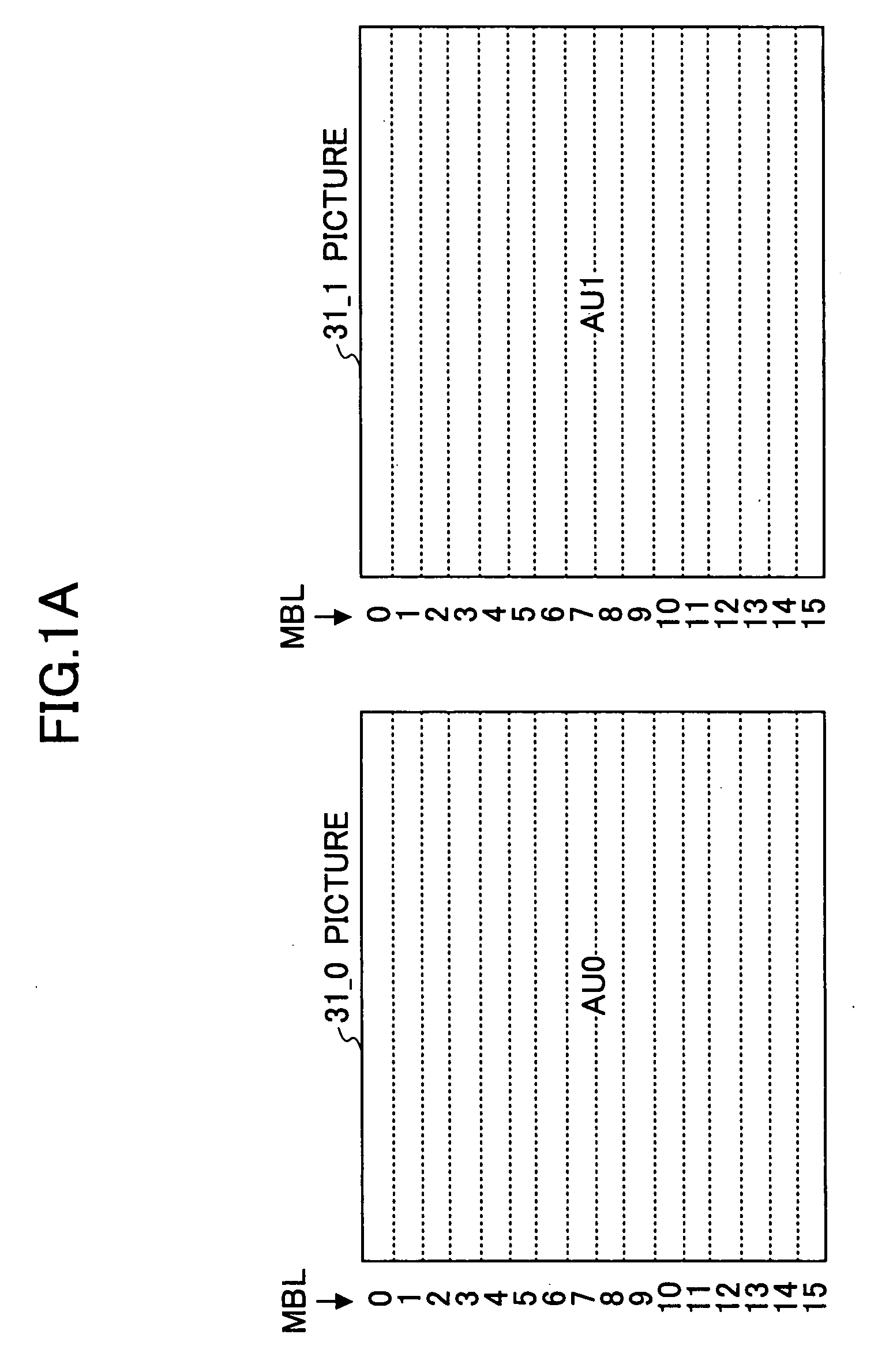
[0044]FIGS. 1A and 1B are drawings for explaining a first embodiment of an MPEG decoder according to the present invention. FIG. 1A shows consecutive pictures 31_0 and 31_1. The picture 31_0 is a picture included in a 0-th access unit AU0, and the picture 31_1 is a picture included in a 1-st access unit AU1.
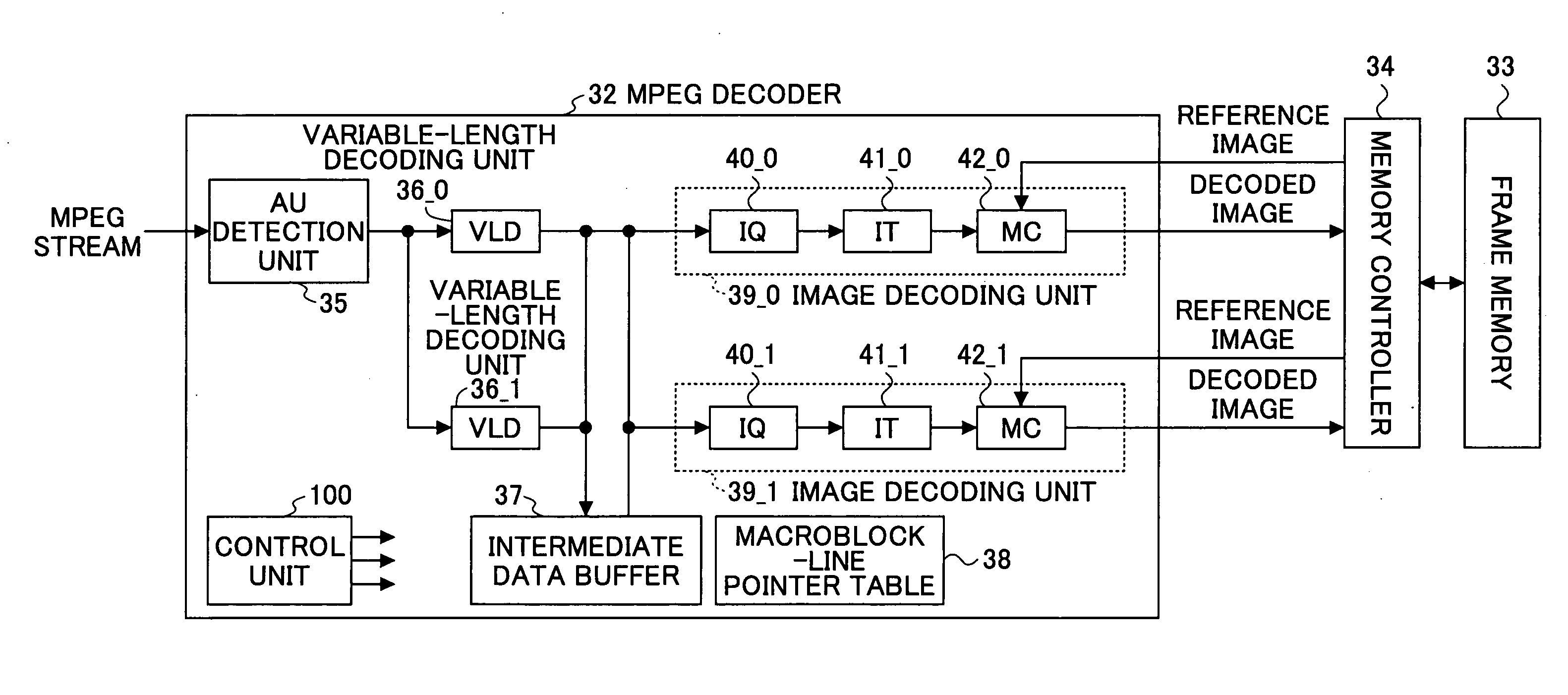
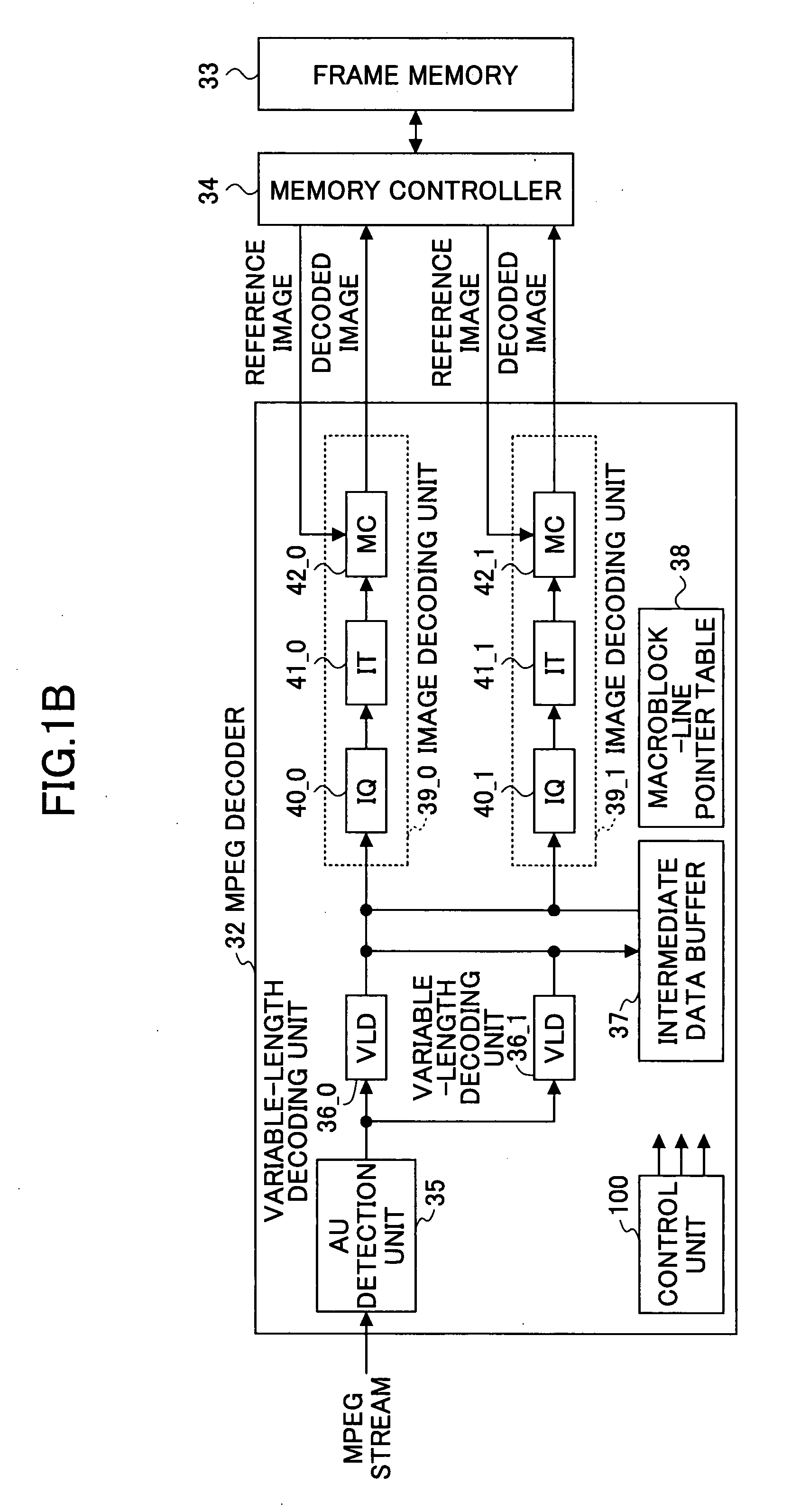
[0045]FIG. 1B shows the first embodiment of an MPEG decoder according to the present invention, and this MPEG decoder 32 serves to decode an MPEG stream that is made by compressing and encoding moving pictures inclusive of the pictures 31_0 and 31_1 according to the MPEG method. A frame memory 33 stores decoded images output from the MPEG decoder 32, and a memory controller 34 controls the storing of decoded images output from the MPEG decoder 32 in the frame memory 33 and the reading of reference images from the frame memory 33.
[0046]In the MPEG decoder 32, an AU (access unit) detection unit 35 detects access units in an MPEG stream that is to be decoded. Variable...
second embodiment
of MPEG Decoder
[0077]FIG. 9 is a drawing for explaining a second embodiment of an MPEG decoder according to the present invention. FIG. 9 shows an MPEG decoder 52 that is the second embodiment of an MPEG decoder according to the present invention. In FIG. 9, a frame memory 53 stores decoded images output from the MPEG decoder 52, and a memory controller 54 controls the storing of decoded images output from the MPEG decoder 52 in the frame memory 53 and the reading of reference images from the frame memory 53.
[0078]The MPEG decoder 52 has the same configuration as the MPEG decoder 32 shown in FIG. 1B that is the first embodiment of an MPEG decoder according to the present invention, except that four image decoding units 39_0 through 39_3 are provided. The image decoding units 39_0 through 39_3 include inverse quantization units (IQ) 40_0 through 40_3, inverse transformation units (IT) 41_0 through 41_3, and motion compensation units (MC) 42_0 through 42_3, respectively.
[0079]A contro...
third embodiment
of MPEG Decoder
[0104]FIG. 12 is a drawing for explaining a third embodiment of an MPEG decoder according to the present invention. FIG. 12 shows an MPEG decoder 62 that is the third embodiment of an MPEG decoder according to the present invention. In FIG. 12, a frame memory 63 stores decoded images output from the MPEG decoder 62, and a memory controller 64 controls the storing of decoded images output from the MPEG decoder 62 in the frame memory 63 and the reading of reference images from the frame memory 63.
[0105]In the MPEG decoder 62, a slice detection unit 65 detects slices in an MPEG stream that is to be decoded. Variable-length decoding units (VLD) 66_0 and 66_1 perform variable-length decoding on a slice-by-slice basis, and an intermediate data buffer 67 stores intermediate data output from the variable-length decoding units 66_0 and 66_1. The intermediate data buffer 67 has a capacity for storing the data of multiple macroblock lines.
[0106]A macroblock-line pointer table 68...
PUM
 Abstract
Description
Claims
Application Information
 - R&D
- Intellectual Property
- Life Sciences
- Materials
- Tech Scout
- Unparalleled Data Quality
- Higher Quality Content
- 60% Fewer Hallucinations
Browse by: Latest US Patents, China's latest patents, Technical Efficacy Thesaurus, Application Domain, Technology Topic, Popular Technical Reports.
© 2025 PatSnap. All rights reserved.Legal|Privacy policy|Modern Slavery Act Transparency Statement|Sitemap|About US| Contact US: help@patsnap.com


