Medical image diagnosis apparatus, and x-ray ct apparatus, and image processor
a technology of x-ray ct and imaging apparatus, which is applied in the field of medical image diagnosis apparatus, x-ray ct apparatus, and image processor, can solve the problem of difficult to specify the position of a liver from the ct image, and achieve the effect of shortening the stand-by tim
- Summary
- Abstract
- Description
- Claims
- Application Information
AI Technical Summary
Benefits of technology
Problems solved by technology
Method used
Image

Examples
first embodiment
[0028]Hereinafter, the invention will be described with reference to the drawings.
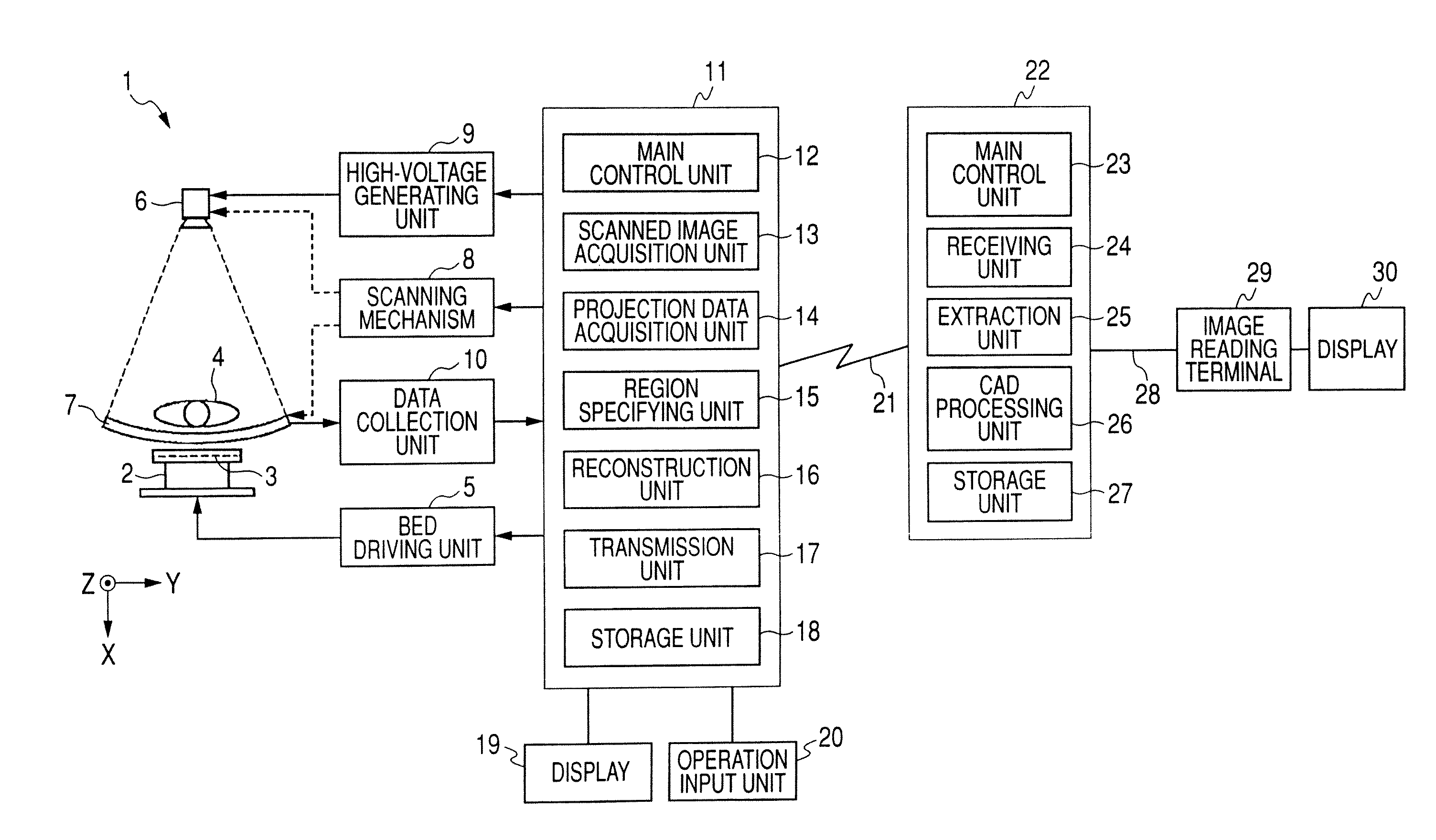
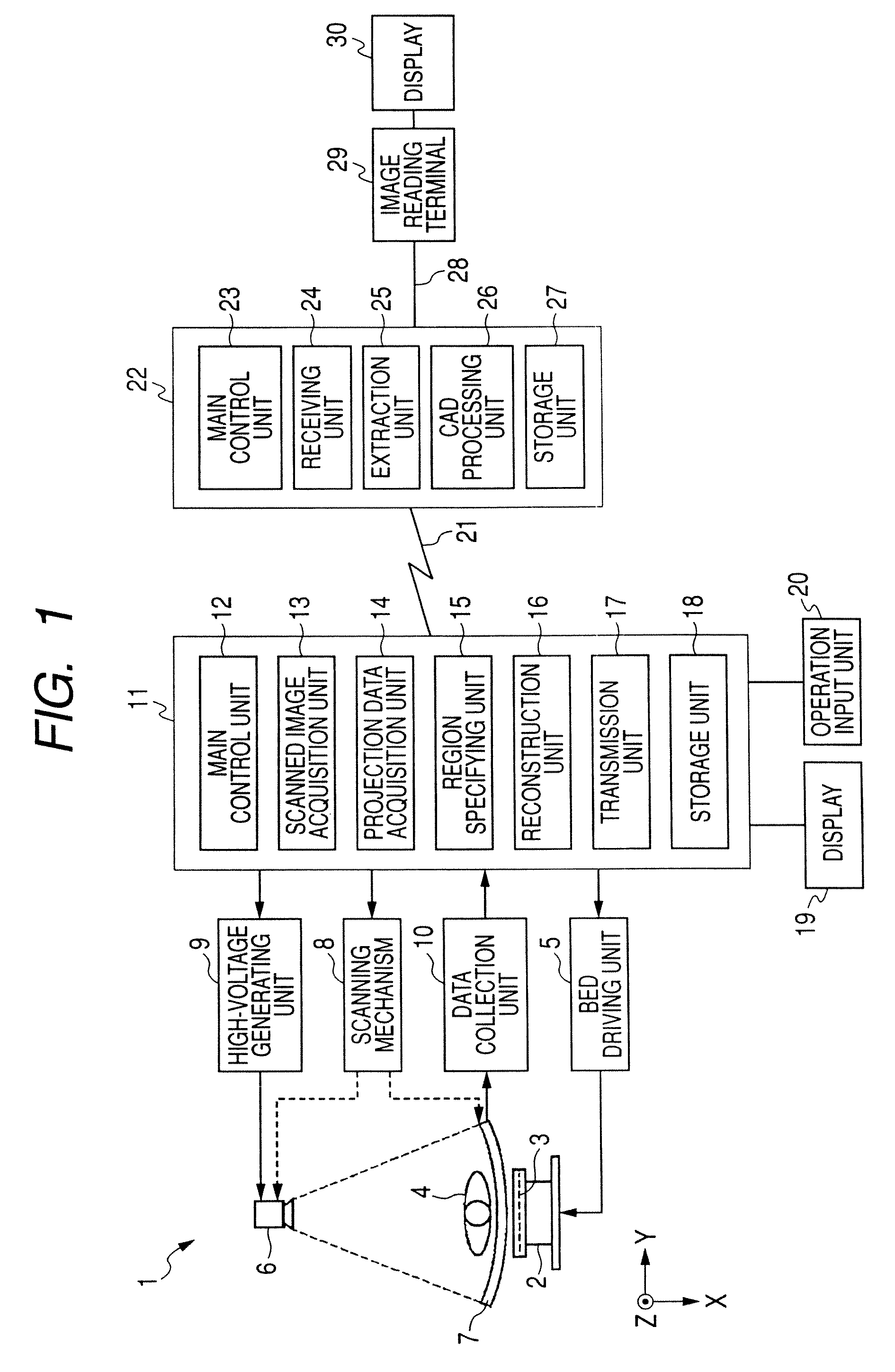
[0029]FIG. 1 shows the overall construction of a computer-aided diagnosis (CAD) apparatus. An X-ray CT apparatus 1 includes a bed 2. A ceiling plate 3 is provided in an upper part of the bed 2 so as to be movable in the Z-direction. A subject 4, such as a patient, is placed on the ceiling plate 3. The bed 2 is provided with a bed driving unit 5. The bed driving unit 5 moves the ceiling plate 3 in the Z-direction when a scanned image is acquired, or when CT scanning, such as helical scanning, is performed to acquire a CT image.
[0030]An X-ray source 6 and an X-ray detector 7 are provided so as to face each other. The X-ray source 6 and the X-ray detector 7 are provided in a scanning mechanism 8. The scanning mechanism 8 performs, for example, helical scanning, that is, continuously rotates the X-ray source 6 and the X-ray detector 7 together. Along with this, the scanning mechanism 8 delivers a movement ...
second embodiment
[0084]Next, the invention will be described with reference to the drawings. In addition, since the construction of the present apparatus is the same as that of FIG. 1, differences will be described by the aid of FIG. 1. The present apparatus detects the feature or part of a disease, such as a liver cancer, in a liver region as a target tissue region in the subject 4, and finds out the feature of the disease numerically.
[0085]The region designating unit 15 displays a scanned image SD shown in, for example, FIG. 8 onto the display 19. A liver Hk is displayed in the scanned image SD. The region designating unit 15 designates, for example, a rectangular frame W as a specific spot M on a scanned image SD by a user's operation instruction from the operation input unit 20 on the display 19. The frame W is designated as a two-dimensional region surrounding the liver Hk.
[0086]The extraction unit 25 projects onto a CT image a frame W designated by the region designating unit 15 through a live...
third embodiment
[0109]Next, the invention will be described with reference to the drawings. In addition, since the construction of the present apparatus is the same as that of FIG. 1, differences will be described by the aid of FIG. 1. The present apparatus detects the feature or part of a disease, such as a liver cancer, in a liver region as a target tissue region in the subject 4, and finds out the feature of the disease numerically.
[0110]The region designating unit 15, as shown in FIG. 11, has a scanned image display unit 30, and an adjusting unit 31. The adjusting unit 31 displays the scanned image SD as shown in FIG. 12 onto, for example, the display 19.
[0111]The adjusting unit 31 allows adjustment of the range of a region that corresponds in positional relationship to a scanned image SD displayed by the scanned image display unit 30, and that is extracted from a CT image for each of a plurality of target tissue regions, for example, a liver, lungs, a large intestines, breasts, main arteries, ...
PUM
 Abstract
Description
Claims
Application Information
 - R&D
- Intellectual Property
- Life Sciences
- Materials
- Tech Scout
- Unparalleled Data Quality
- Higher Quality Content
- 60% Fewer Hallucinations
Browse by: Latest US Patents, China's latest patents, Technical Efficacy Thesaurus, Application Domain, Technology Topic, Popular Technical Reports.
© 2025 PatSnap. All rights reserved.Legal|Privacy policy|Modern Slavery Act Transparency Statement|Sitemap|About US| Contact US: help@patsnap.com