System and method for providing failure protection in optical networks

a technology of optical network and failure protection, applied in the field of telecommunication techniques, can solve the problems of relatively high cost of some important components of optical access communication network, and achieve the effect of improving reliability and/or robustness of downlink and efficient solving

Active Publication Date: 2008-03-13
HUAWEI TECH CO LTD
View PDF9 Cites 9 Cited by
  • Summary
  • Abstract
  • Description
  • Claims
  • Application Information

AI Technical Summary

Benefits of technology

[0017]Many benefits are achieved by way of the present invention over conventional techniques. Some embodiments of the present invention can economically and / or efficiently solves problems of a random optical transmitter and / or receiver failure in the Central Office (CO). Certain embodiments of the present invention can improve reliability and / or robustness of downlink and / or uplink data communication in an optical network. Some embodiments of the present invention do not impose additional requirements on the regular optical transmitters and / or receivers for providing protection. Certain embodiments of the present invention do not impose additional requirements on a multiplexer and demultiplexer for providing protection. Some embodiments of the present invention do not impose demanding requirements on the emission power of a tunable optical transmitter. Certain embodiments of the present invention provide M:N protection by using M tunable optical transmitters for N regular wavelength channels. For example, 1≦M<N. Some embodiments of the present invention do not require a system for signal transmission and a system for signal reception each have an optical channel protection module in a parallel manner. Certain embodiments of the present invention do not need to send a changeover request to the optical channel protection modules of both a transmission system and a reception system in a parallel manner. Some embodiments of the present invention provide failure protection for data transmission by transmitter changeover, instead of by wavelength changeover. Certain embodiments of the present invention provide failure protection for data reception by receiver changeover, instead of by wavelength changeover.

Problems solved by technology

However, the cost for some of the important components of the optical access communication network is relatively high.

Method used


Image

  • System and method for providing failure protection in optical networks
  • System and method for providing failure protection in optical networks
  • System and method for providing failure protection in optical networks

Examples


Embodiment Construction

[0029]The present invention relates in general to telecommunication techniques. More particularly, the invention provides a system and method for providing failure protection. Merely by way of example, the invention is described as it applies to optical networks, such as Wavelength Division Multiplex Passive Optical Networks, but it should be recognized that the invention has a broader range of applicability.

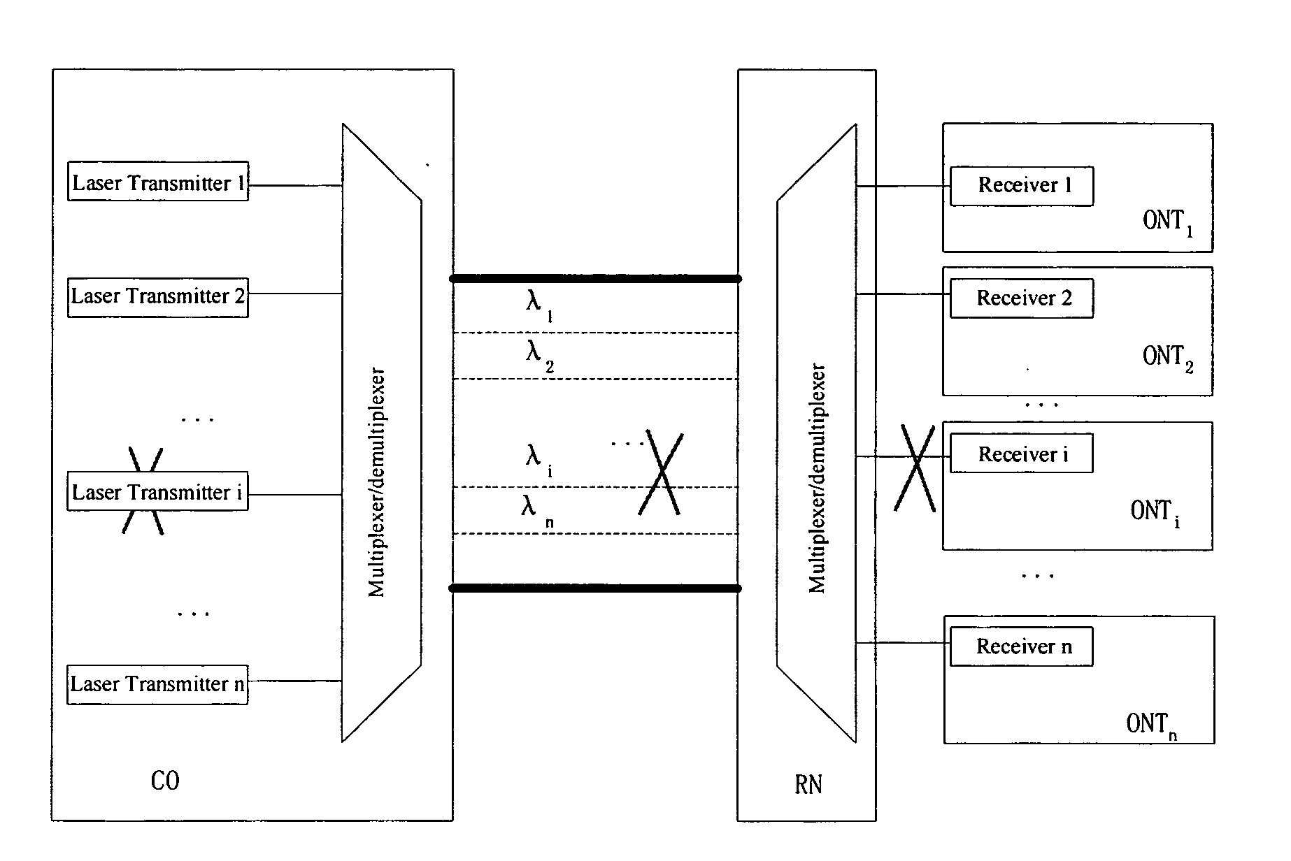
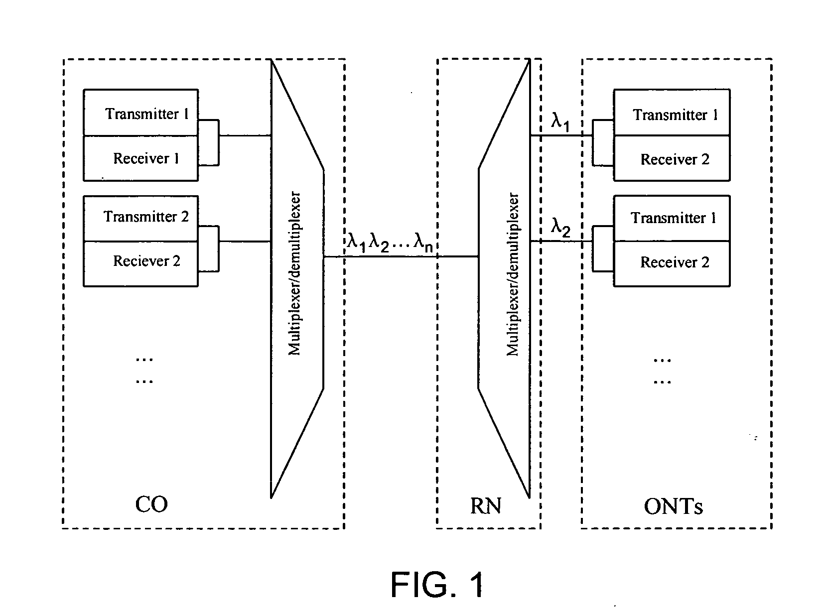
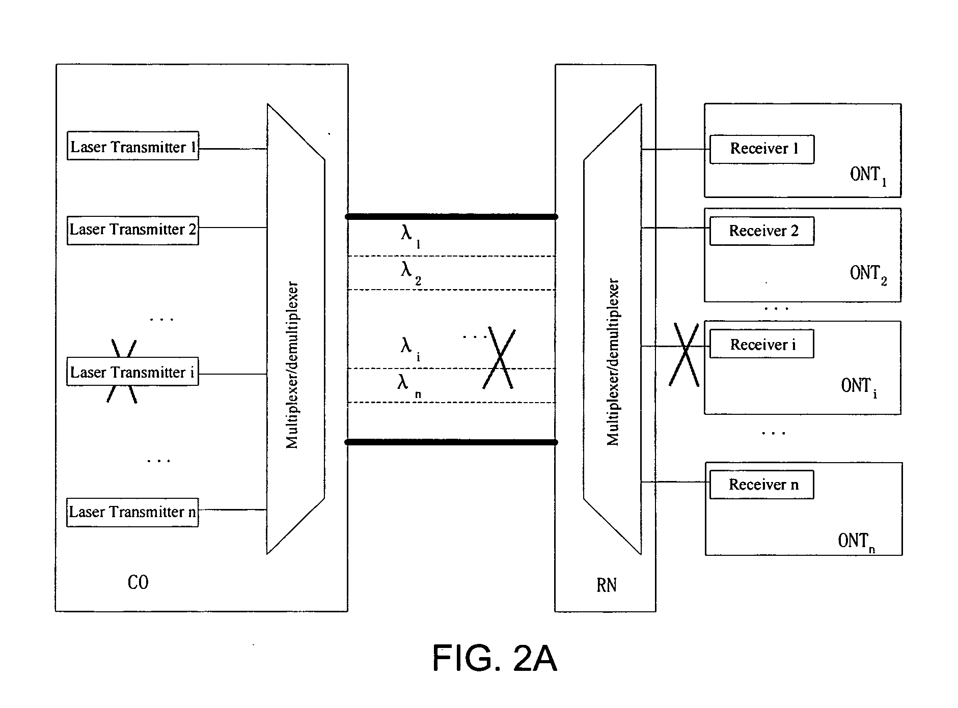
[0030]As shown in FIG. 1, the number of transmitters and receivers in the CO increases with the ever increasing number of channels (or the number of wavelengths). Therefore, the requirement for operation reliability of the transmitters and the receivers often is high. As shown in FIGS. 2(A) and (B), the WDM system often needs to send a channel changeover request to both the transmission system and the reception system in a parallel manner. Therefore the changeover process sometimes can be complicated.

[0031]FIG. 3 is a simplified system for providing failure protection according ...


PUM


Abstract

A system and method for transmitting an optical signal. The system includes a first optical transmitter capable of transmitting a first optical signal under one or more first operating conditions, and the first optical signal corresponds to a first wavelength. Additionally, the system includes a second optical transmitter capable of transmitting a second optical signal under one or more second operating conditions, and the second optical signal corresponds to a second wavelength. Moreover, the system includes an optical multiplexer coupled to the first optical transmitter and the second optical transmitter and capable of generating a multiplexed optical signal, a detection component configured to determine at least whether the first optical transmitter satisfies one or more predetermined conditions, and a tunable optical transmitter capable of transmitting a third optical signal. The third optical signal corresponds to a third wavelength.

Description

CROSS-REFERENCES TO RELATED APPLICATIONS[0001]NOT APPLICABLESTATEMENT AS TO RIGHTS TO INVENTIONS MADE UNDER FEDERALLY SPONSORED RESEARCH OR DEVELOPMENT[0002]NOT APPLICABLEREFERENCE TO A “SEQUENCE LISTING,” A TABLE, OR A COMPUTER PROGRAM LISTING APPENDIX SUBMITTED ON A COMPACT DISK[0003]NOT APPLICABLEBACKGROUND OF THE INVENTION[0004]The present invention relates in general to telecommunication techniques. More particularly, the invention provides a system and method for providing failure protection. Merely by way of example, the invention is described as it applies to optical networks, such as Wavelength Division Multiplex Passive Optical Networks, but it should be recognized that the invention has a broader range of applicability.[0005]Recently, the demand for broadband access operations has increased rapidly. In order to meet the demand for high-bandwidth and high-capacity access, the industry often chooses the optical access communication network. However, the cost for some of the...

Claims


Application Information

Patent Timeline
Patent Type & Authority Applications(United States)
IPC IPC(8): H04B10/00
CPCH04B10/032H04J14/0226H04J14/025H04J14/0297H04J14/0246H04J14/0282
Inventor WEI, GUOZHANG, XULIANGJIANG, TAOZHAO, JUNHUANG, WEICHEN, JUNWANG, YUNTAOLIN, HUAFENGWANG, FENG
Owner HUAWEI TECH CO LTD
Why Eureka
Try Eureka