Control system architecture for a hybrid powertrain

Inactive Publication Date: 2008-03-13
ELECTRONICS DATA SYST CORP +1
View PDF10 Cites 246 Cited by
  • Summary
  • Abstract
  • Description
  • Claims
  • Application Information

AI Technical Summary

Benefits of technology

[0015]Another aspect of the invention comprises the system controller operable to communicate directly with the first and second motor control processors

Problems solved by technology

Other issues include having a control system which meets quality, reliability and durability targets,

Method used


Image

  • Control system architecture for a hybrid powertrain
  • Control system architecture for a hybrid powertrain
  • Control system architecture for a hybrid powertrain

Examples


Embodiment Construction

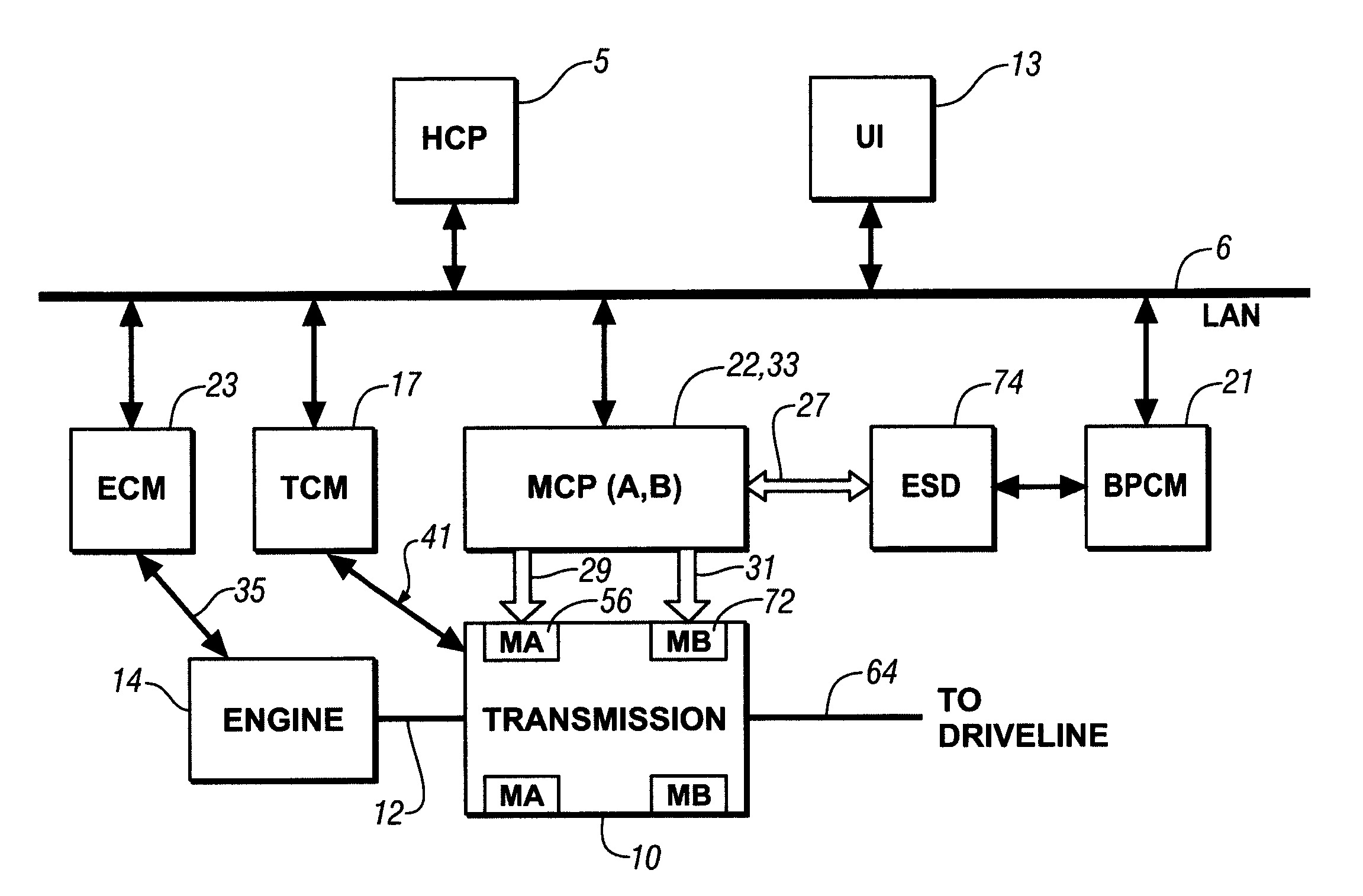
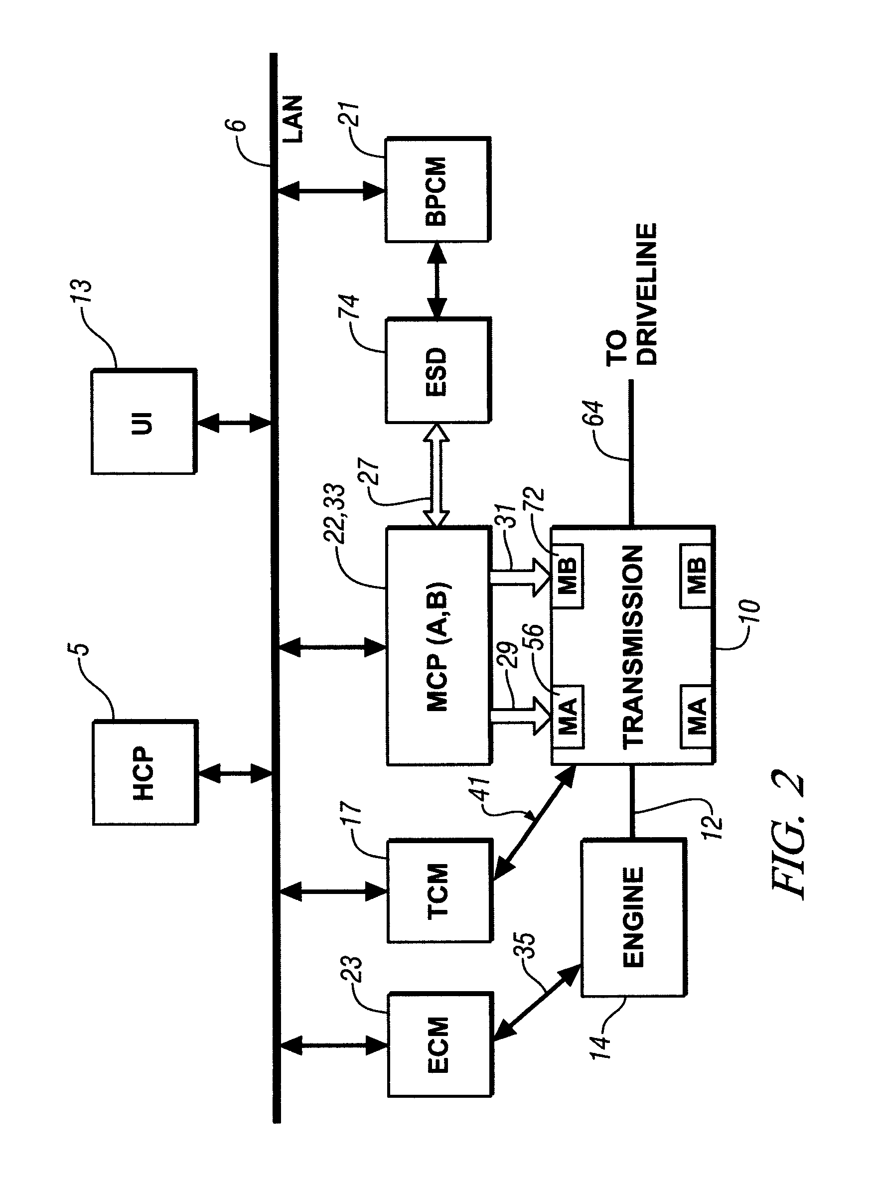
[0024]Referring now to the drawings, wherein the showings are for the purpose of illustrating the invention only and not for the purpose of limiting the same, FIGS. 1 and 2 show a system comprising an engine 14, transmission 10, control system, and driveline which has been constructed in accordance with an embodiment of the present invention.

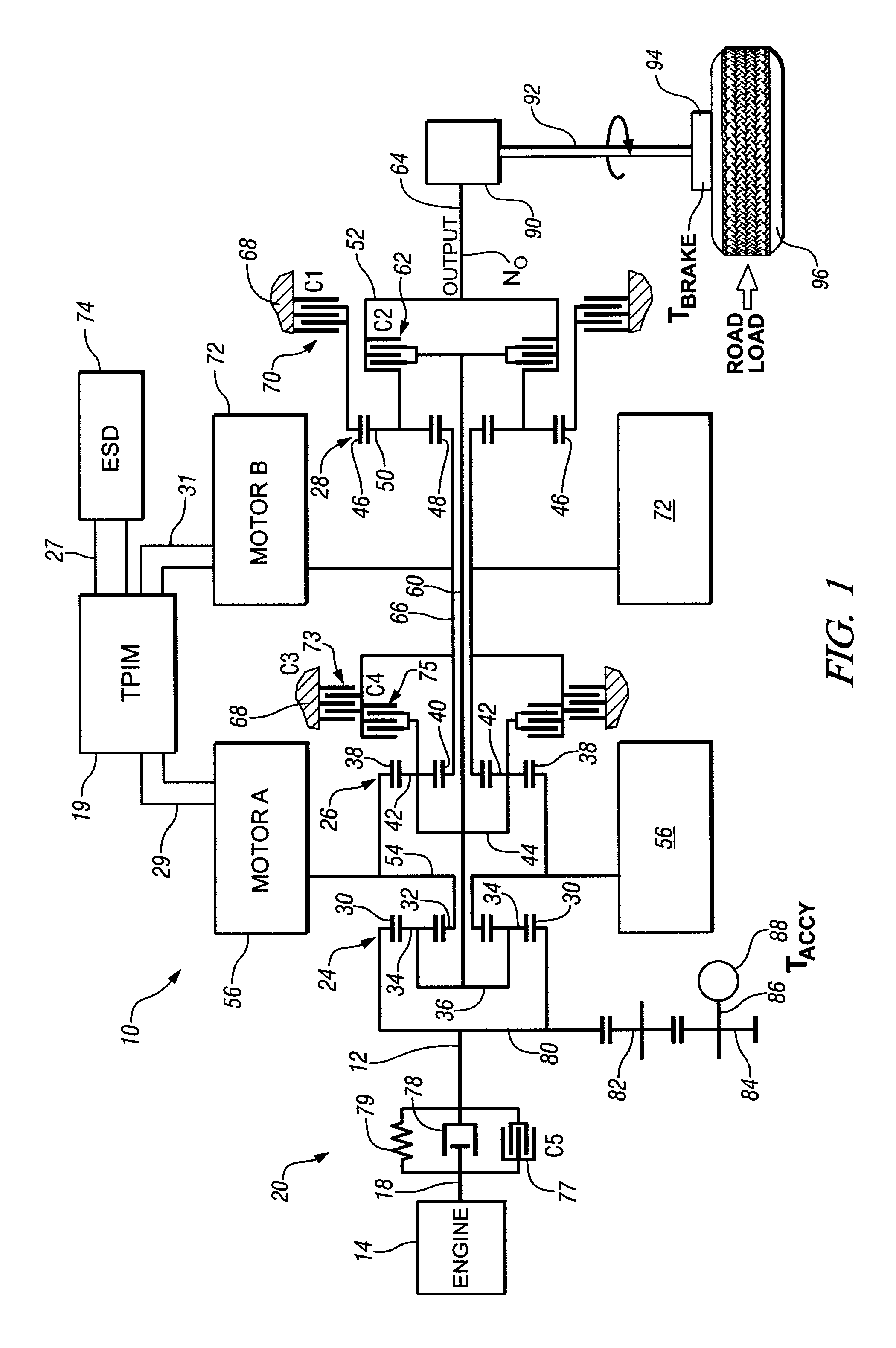
[0025]Mechanical aspects of exemplary transmission 10 are disclosed in detail in commonly assigned U.S. Patent Application Publication No. U.S. 2005 / 0137042 A1, published Jun. 23, 2005, entitled Two-Mode, Compound-split Hybrid Electro-Mechanical Transmission having Four Fixed Ratios, which is incorporated herein by reference. The exemplary two-mode, compound-split, electro-mechanical hybrid transmission embodying the concepts of the present invention is depicted in FIG. 1, and is designated generally by the numeral 10. The hybrid transmission 10 has an input member 12 that may be in the nature of a shaft which receives motive torque from an inte...


PUM


Abstract

A control apparatus for a powertrain system comprising an engine and two electrical machines operably coupled to a two-mode compound-split electro-mechanical transmission is provided. It includes a system controller and two motor control processors. The system controller communicates with the motor control processors via two high speed communications buses and directly-linked serial peripheral interface buses. The motor control processors control flow of electrical power between the electrical machines and an electrical energy storage device. A second control device is operable to control the engine, preferably to control torque output. The internal combustion engine preferably has a crank position sensor which is signally connected to a dedicated input to the second control device and to a dedicated input to the system controller of the first control device.

Description

TECHNICAL FIELD[0001]This invention pertains generally to vehicle powertrain systems, and more specifically to a control system for a hybrid transmission system for a vehicle.BACKGROUND OF THE INVENTION[0002]Various hybrid powertrain architectures are known for managing the input and output torques of various prime-movers in hybrid vehicles, most commonly internal combustion engines and electric machines. Hybrid powertrain systems are generally characterized by an internal combustion engine and one or more electrical machines which provide motive torque to a vehicle driveline using a transmission device.[0003]One parallel-hybrid powertrain architecture comprises a two-mode, compound-split, electro-mechanical transmission which has an input member for receiving motive torque from a source, e.g. an internal combustion engine, and an output member for delivering motive torque from the transmission, typically to a driveline of a vehicle. First and second electrical machines comprising m...

Claims


Application Information

Patent Timeline
IPC IPC(8): B60W10/02
CPCB60W10/06B60W10/08B60W10/26B60W20/00Y10T477/26B60W2710/086Y02T10/6286Y10T477/23B60W2710/0666Y02T10/62B60W10/30B60W2510/083B60W2510/06
Inventor CAWTHORNE, WILLIAM R.MAIORANA, MARIO V.SAH, JY-JEN F.GLEASON, SEAN E.HUBBARD, GREGORY A.WOZNIAK, LEONARD G.BOYLE, MATTHEW T.HEAP, ANTHONY H.KOTHARI, ANIKET
Owner ELECTRONICS DATA SYST CORP
Why Eureka
Try Eureka