
High capacity debulking catheter with distal driven cutting wheel

a cutting wheel and catheter technology, applied in catheters, surgical forceps, therapy, etc., can solve the problems of non-intuitive distance driven designs, etc., and achieve the effects of less stress on patients and physicians, improved catheter ability, and faster plaque removal

Inactive Publication Date: 2008-03-13
TYCO HEALTHCARE GRP LP
View PDF99 Cites 204 Cited by
  • Summary
  • Abstract
  • Description
  • Claims
  • Application Information

AI Technical Summary

Benefits of technology

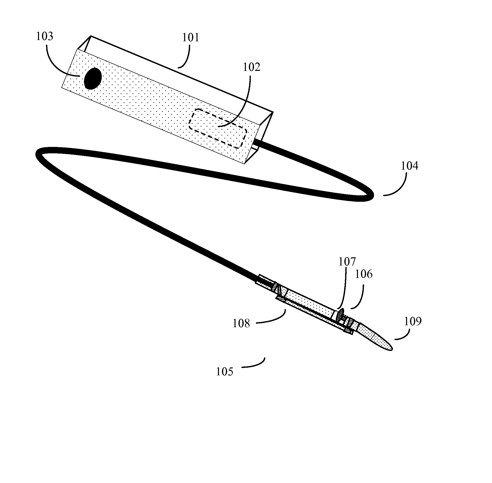
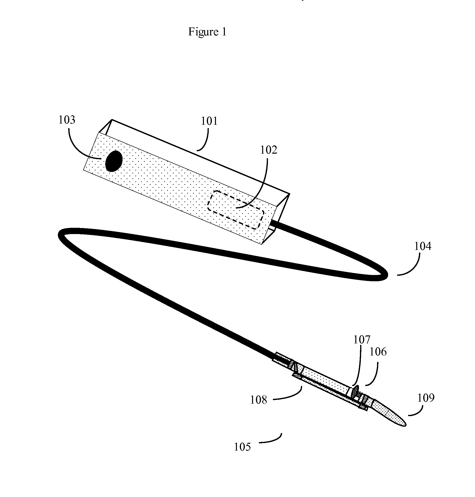
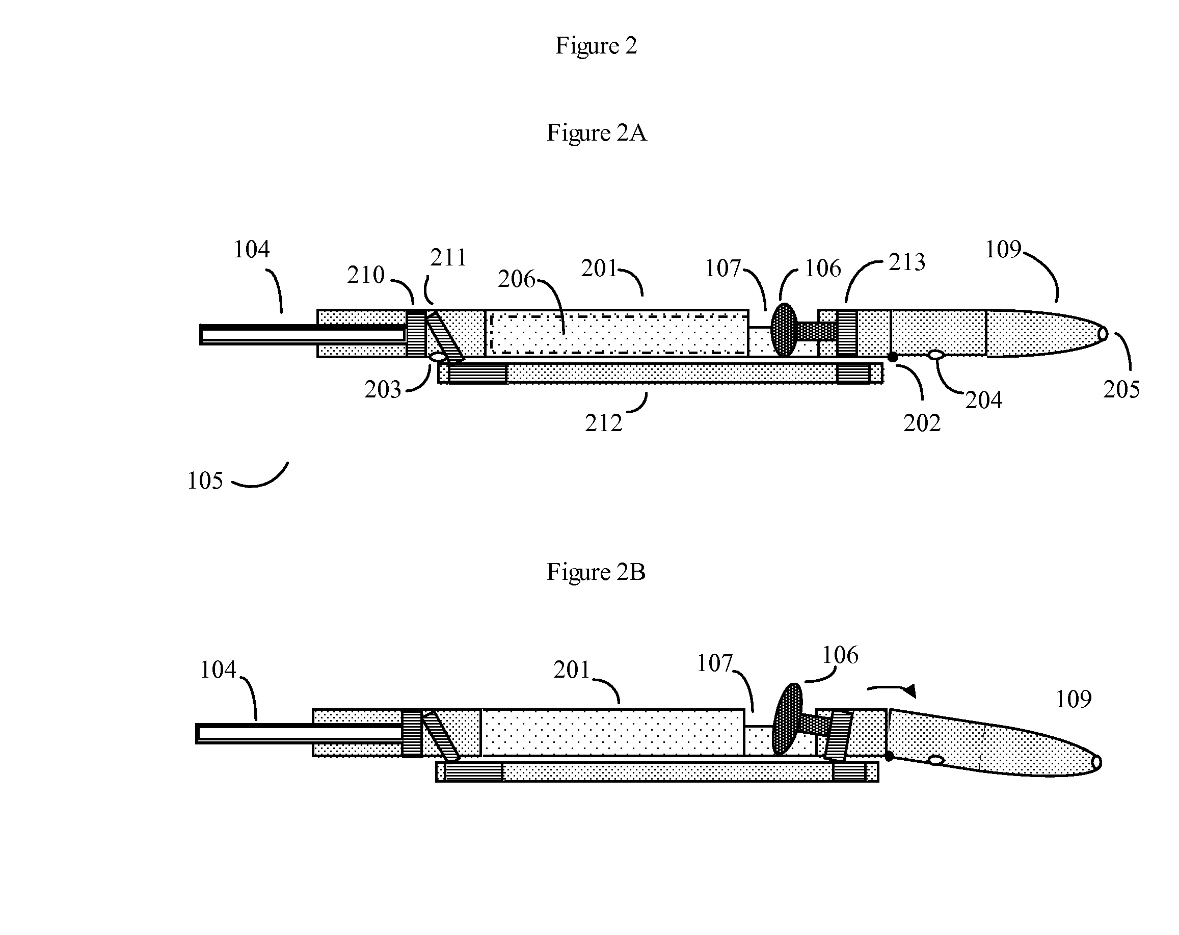
[0018] The present art teaches that such non-intuitive distal or circumference driven designs, although more complex, can have the unexpected advantage of now allowing plaque shavings to be stored in the larger volume hollow catheter body, rather than the limited catheter nose space. In some embodiments, even hollow tube of the catheter may be used for still more additional storage space.
[0019] This new design substantially increases the ability of the catheter to hold plaque shavings. This in turn translates into a direct benefit to both physicians and patients. The improved catheter can be operated for an appreciably longer period of time (i.e. clear substantially more plaque) before the operator needs to withdraw the catheter from the body for cleaning. This makes plaque procedures quicker, cheaper, more effective, (because more plaque can now be removed without undue hardship) and less stressful to patients and physicians. It also encourages more complete and careful plaque removal.
[0020] A second advantage is that distal driven designs can also give the catheter an improved ability to trim dangling portions of plaque residue that are still hanging to artery walls.
[0021] In an alternative embodiment of the present invention, sensors may also be added to the design to help the operator properly position the device and also properly orient the cutting window of the device.

Problems solved by technology

Such distally (or circumference) driven designs are very non-intuitive, which is one of the reasons why prior art ignored or taught against such designs.

Method used


Image

  • High capacity debulking catheter with distal driven cutting wheel
  • High capacity debulking catheter with distal driven cutting wheel
  • High capacity debulking catheter with distal driven cutting wheel

Examples


Embodiment Construction

[0029] The present art is normally intended for use with human patients, as well as various veterinary applications. For simplicity, this combined human or animal use will be referred to as use in mammals, although of course such devices could also be used in appropriate non-mammal animals such as birds, reptiles, and amphibians, etc., as appropriate.

[0030] It should also be understood that although the examples of cutting unwanted plaque deposits in arteries are used throughout this disclosure, the actual invention may be used for a broader variety of applications, including removing tumors, getting biopsies, etc. in arteries, veins, and any other tubular or roughly tubular body lumen.

[0031] For brevity, non-proximally driven rotating cutter catheters will usually be referred to in the specification as distal driven designs. However it should be understood that wherever appropriate, alternative non-proximally driven designs such as circumference driven designs are also included i...


PUM


Abstract

The present invention is an atherectomy catheter with a rotary cutting knife that is driven from the distal (nose) or side (circumference) direction. The catheter collects plaque shavings in a hollow collection chamber mounted in between the rotary cutting knife and the main catheter tubing. In contrast to prior art designs, which utilized nose mounted plaque collection chambers, the present design is able to store a substantially larger volume of removed plaque, thus increasing the length of time and amount of plaque removal that can be accomplished before the catheter must be removed from the body and cleaned. This decreases medical procedure time, allows for more complete and careful plaque removal, and reduces the burden on the patient and physician.

Description

RELATED U.S. APPLICATION DATA [0001] The present application is a continuation in part of, and claims the priority benefit of, U.S. application Ser. No. 10 / 896,471, filed Jul. 21, 2004. Application Ser. No. 10 / 896,471 was a continuation in part of, and claimed the priority benefit of, Application Ser. No. 10 / 288,559 filed Nov. 4, 2002. Application Ser. No. 10 / 288,559 was a continuation in part of, and claimed the priority benefit of, application Ser. No. 10 / 027,418, filed on Dec. 19, 2001. Application Ser. No. 10 / 027,418 in turn claimed the priority benefit of Provisional Patent Application Ser. No. 60 / 257,704, filed Dec. 20, 2000, entitled “Debulking Catheter” and Provisional Patent Application Ser. No. 60 / 272,273 filed Feb. 27, 2001. The complete disclosures of all references (Ser. Nos. 10 / 896,471; 10 / 288,559; 10 / 027,418; 60 / 257,704 and 60 / 272,273) are incorporated herein by reference.BACKGROUND OF THE INVENTION [0002] Restriction of blood circulation due to the atherosclerotic bu...

Claims


Application Information

Patent Timeline
IPC IPC(8): A61B17/22A61B17/00A61B17/28A61B17/32A61B18/14
CPCA61B17/320758A61B17/320783A61B2017/00685A61B2017/320791A61B2017/320032A61B2017/320775A61B2017/2927A61B8/12A61B17/2202A61B17/320725
Inventor OLSON, WILLIAM JOHN
Owner TYCO HEALTHCARE GRP LP
Learn More