RFID detection and identification system for implantable medical lead systems

a technology of implantable medical devices and detection systems, applied in the field of radio frequency identification (rfid) tags, can solve the problems of limited information so provided, serious dilemma for the er, and inability to reliably identify the form of identification

Inactive Publication Date: 2008-03-13
WILSON GREATBATCH LTD
View PDF80 Cites 252 Cited by
  • Summary
  • Abstract
  • Description
  • Claims
  • Application Information

AI Technical Summary

Benefits of technology

[0014] The present invention is directed to systems for identifying medical implants within a patient and/or retrieving medical information from a patient, comprising an implantable medical device and/or lead wire system, a radio frequency identification (RFID) tag having an antenna and being associated with the implantable medical device or lead wire system, the RFID tag containing information relating to the patient and/or the implantable medical device or lead wire system, and an interrogator capable of communicating with the RFID tag. With informed patient consent, patient information can include the na

Problems solved by technology

The information so provided is limited due to space and typically includes only the manufacturer and model number of the implanted device.
However, such forms of identification are often not reliable.
In addition, there have been a number of situations where the patient (due to dementia or Alzheimer's, etc.) cannot clearly state that he or she even has a pacemaker.
If the patient is comatose, has low blood pressure, or is in another form of cardiac distress, this presents a serious dilemma for the ER.
What happens next is both laborious and time consuming.
It is a very difficult surgical procedure to actually remove leads from the heart once they are implanted.
This is because the distal TIP of the lead wires tend to become embedded and overgrown by myocardial tissue.
It often takes very complex surgical procedures, including open heart surgery, to remove such lead wire s

Method used


Image

  • RFID detection and identification system for implantable medical lead systems
  • RFID detection and identification system for implantable medical lead systems
  • RFID detection and identification system for implantable medical lead systems

Examples


Embodiment Construction

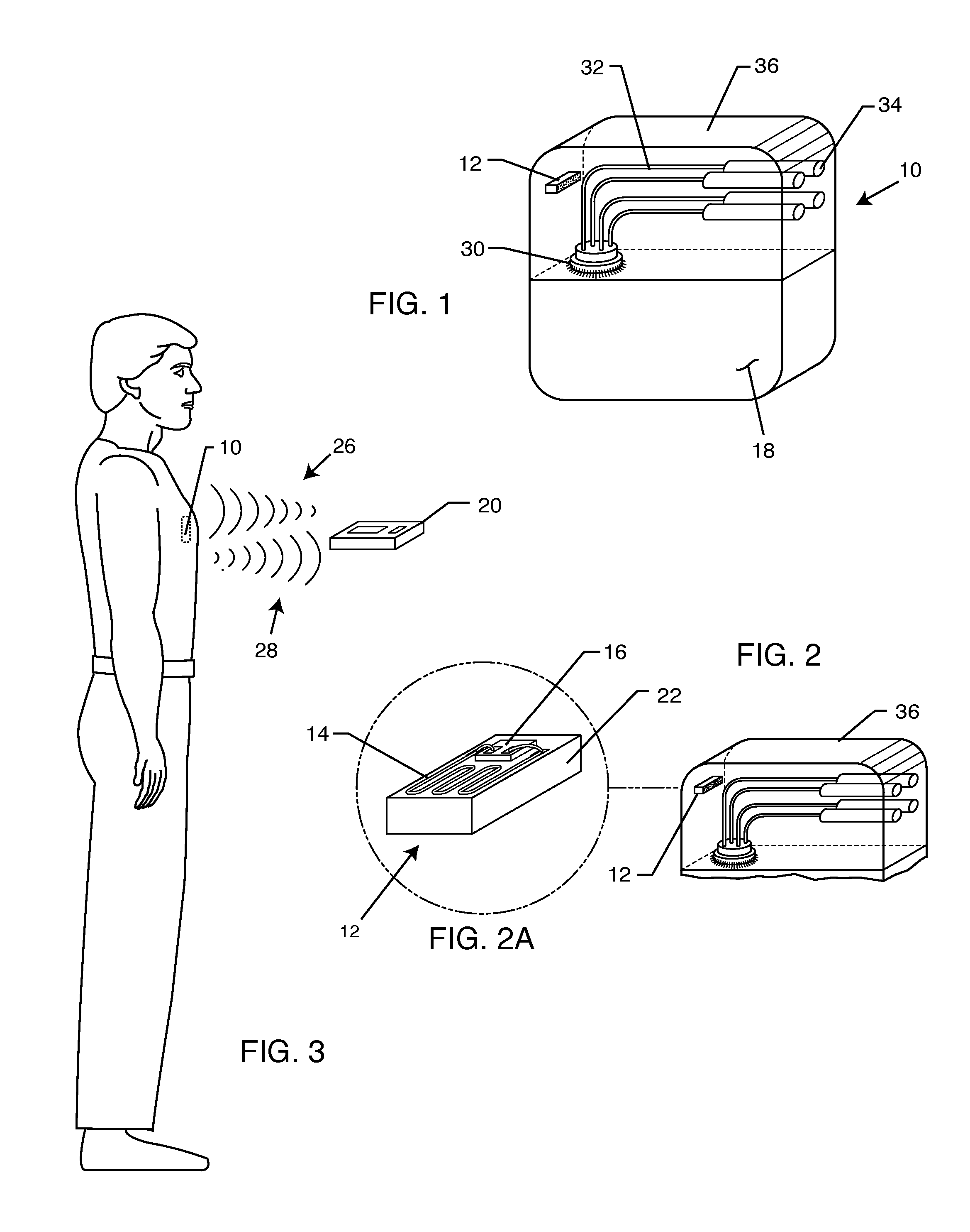
[0066] The present invention is directed to a radio frequency identification (RFID) system for use with active implantable medical devices (AIMDs) and implantable lead wire systems. Specifically, the RFID system comprises an RFID tag implanted in a patient's body and associated with an implanted AIMD or lead wire system, and an interrogator in communication with the RFID tag.

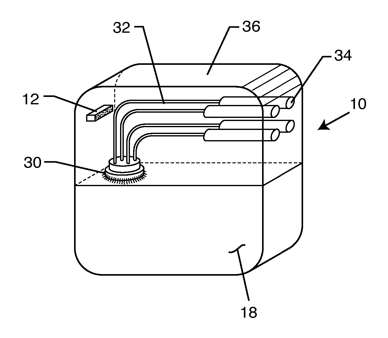
[0067]FIG. 1 is an isometric view of a typical AIMD 10, such as a cardiac pacemaker. Cardiac pacemakers typically have a metallic housing 18 which can be of titanium, stainless steel or the like. This metallic housing 18 is laser welded shut and generally contains a hermetic feedthrough terminal 30 for passage of lead wires 32 into the interior of the metallic housing 18. Said hermetic feedthrough terminals 30 are well known in the art and are generally laser welded into the metallic housing 18 of the implantable medical device. The lead wires 32 as shown in FIG. 1, are generally routed to connectors 34. The co...


PUM


Abstract

A system for identifying active implantable medical devices (AIMD) and lead systems implanted in a patient using a radio frequency identification (RFID) tag having retrievable information relating to the AIMD, lead system and/or patient. The RFID tag may store information about the AIMD manufacturer, model number, serial number; lead wire system placement information and manufacturer information; MRI compatibility due to the incorporation of bandstop filters; patient information, and physician and/or hospital information and other relevant information. The RFID tag may be affixed or disposed within the AIMD or lead wires of the lead system, or surgically implanted within a patient adjacent to the AIMD or lead wire system.

Description

BACKGROUND OF THE INVENTION [0001] This invention relates generally to methods of identifying implanted medical devices and implantable lead wires and systems. More specifically, this invention relates to radio frequency identification (RFID) tags for use with medical devices and lead systems implanted in a patient. [0002] There are known in the art various methods for identifying implanted medical devices. One such method is the use of X-ray identification tags encapsulated within header blocks of pacemakers or implantable cardioverter defibrillators (ICD). Such X-ray identification tags can be read on an X-ray of the implanted device and provide information to the physician. The information so provided is limited due to space and typically includes only the manufacturer and model number of the implanted device. [0003] It would be beneficial if physicians were able to obtain additional information about an implanted device and / or a patient from an implanted identification tag. Such...

Claims


Application Information

Patent Timeline
IPC IPC(8): A61N1/00
CPCA61B1/00059A61B5/0031A61B19/44A61B2019/448A61B2562/08A61N2001/086A61N1/08A61N1/37223A61N1/37252A61N1/3752A61N1/3754A61N1/056A61B90/90A61B90/98A61N1/086A61N1/37254
Inventor STEVENSON, ROBERT A.
Owner WILSON GREATBATCH LTD
Why Eureka
Try Eureka