
Controlled material removal rate (CMRR) and self-tuning force control in robotic machining process

a robotic machining and self-tuning force technology, applied in the field of robots, can solve the problems of reducing the stiffness of industrial robots, and affecting the operation of robotic machining processes

Inactive Publication Date: 2008-03-13
ABB RES LTD
View PDF9 Cites 51 Cited by
  • Summary
  • Abstract
  • Description
  • Claims
  • Application Information

AI Technical Summary

Problems solved by technology

As is described in U.S. patent application Ser. No. 11 / 220,174 filed on Sep. 6, 2005 and entitled “Robotic Machining With A Flexible Manipulator” (“the '174 application”), the disclosure of which is hereby incorporated herein by reference, the lower stiffness of industrial robots presents a disadvantage for a robotic machining process as compared to CNC machines.
Therefore, improving the rate at which material is removed and minimizing process interruptions due to premature tool wear or failure can decrease the machining time.
Since most foundry parts have irregular shapes and uneven depth-of-cut, this will introduce a dramatic change of MRR, which results in a very conservative selection of machining parameters to avoid tool breakage, spindle overload and robot vibration.
Because of the foregoing reason, fixed-gain controllers have difficulties in maintaining consistent system performance and stability for a wide range of cutting conditions.
During the last two decades, many adaptive and robust control techniques were developed in order to deal with the problems of fixed-gain controllers, but very few of them have been commercialized into products due to the complexity of the controller and the process.
The robust control of this technique is easy to implement, but it does not guarantee consistent control performance, as compared to adaptive control.
To successfully use this technique the process parameter changes, that is the depth of the cut, need to be known in advance to maintain tight performance bounds, which is not easy to achieve or not cost effectively achieved for many machining applications.

Method used


Image

  • Controlled material removal rate (CMRR) and self-tuning force control in robotic machining process
  • Controlled material removal rate (CMRR) and self-tuning force control in robotic machining process
  • Controlled material removal rate (CMRR) and self-tuning force control in robotic machining process

Examples


Embodiment Construction

[0059]As will be appreciated by one of skill in the art, the present invention may be embodied as a method, system, or computer program product. Accordingly, the present invention may take the form of an entirely hardware embodiment, an entirely software embodiment (including firmware, resident software, micro-code, etc.) or an embodiment combining software and hardware aspects that may all generally be referred to herein as a “circuit,”“module” or “system.”

[0060]Furthermore, the present invention may take the form of a computer program product on a computer-usable or computer-readable medium having computer-usable program code embodied in the medium. The computer-usable or computer-readable medium may be any medium that can contain, store, communicate, propagate, or transport the program for use by or in connection with the instruction execution system, apparatus, or device and may by way of example but without limitation, be an electronic, magnetic, optical, electromagnetic, infra...


PUM


Abstract

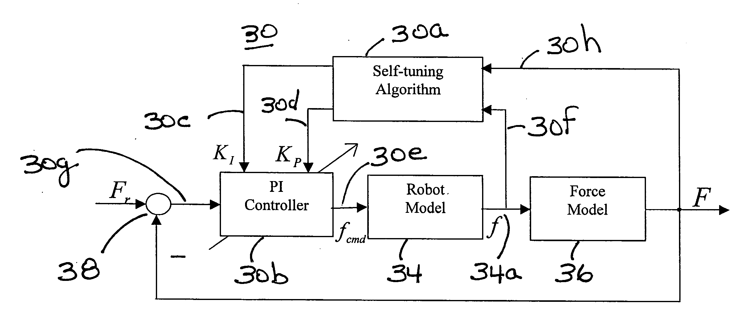
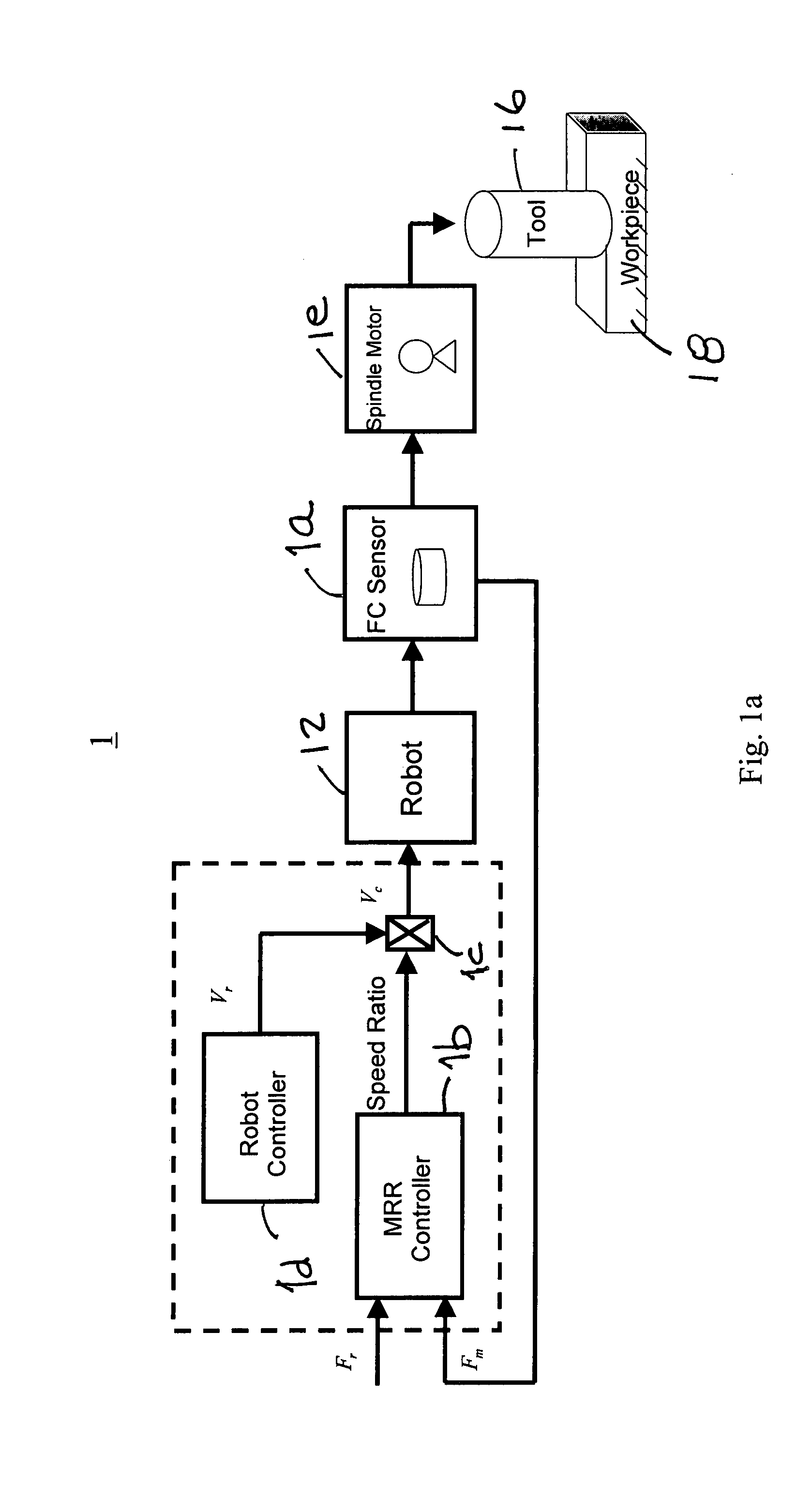
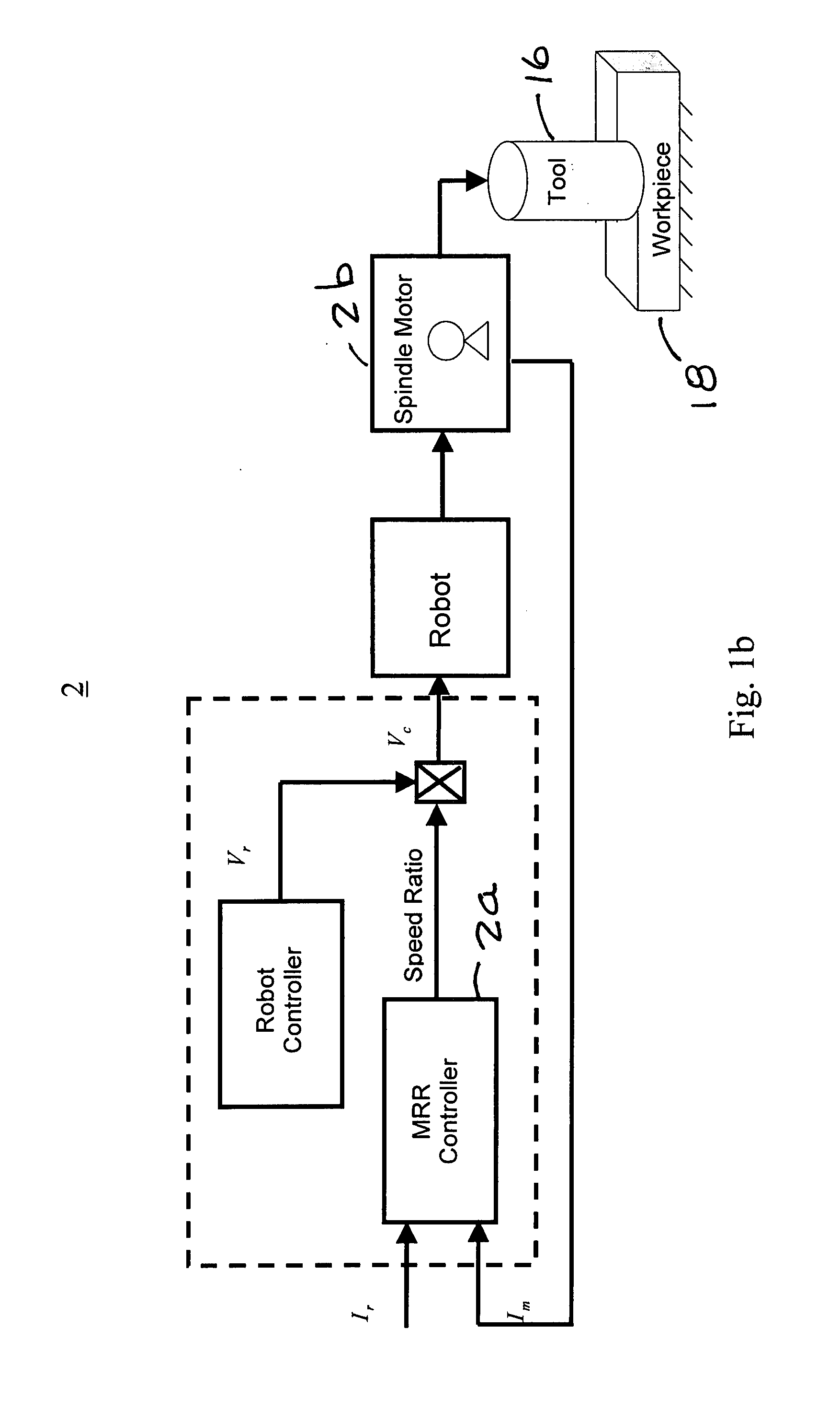
A method and apparatus for a robotic machining process that gives a controlled removal rate of material from a workpiece when an object, tool or workpiece, held by a robot is brought into contact with a stationary object, workpiece or tool. A signal indicative of the force applied by the held object t the stationary object is used to control the rate at which the robot moves the held object in relation to the stationary object. Associated with the robot is a controller that has tunable proportional and integral gains. The controller determines a command for the feed rate of the tool when the tool engages the workpiece. In response to that command, the proportional and integral gains are tuned to obtain a cutting force to be applied to the workpiece when the tool engages the workpiece that is substantially the same as a desired cutting force.

Description

FIELD OF THE INVENTION[0001]This invention relates to robots and more particularly to automatic control of a robotic machining process.DESCRIPTION OF THE PRIOR ART[0002]Industrial robots are used to perform machining tasks because of their programmability, adaptability, flexibility, and their relatively low cost. As is described in U.S. patent application Ser. No. 11 / 220,174 filed on Sep. 6, 2005 and entitled “Robotic Machining With A Flexible Manipulator” (“the '174 application”), the disclosure of which is hereby incorporated herein by reference, the lower stiffness of industrial robots presents a disadvantage for a robotic machining process as compared to CNC machines. Thus, advanced control technologies were developed in order to meet the challenges of using industrial robots to perform machining tasks. One example of such an advanced control technology is described in the '174 application.[0003]Machining processes, such as grinding, deburring, polishing, turning, and milling, w...

Claims


Application Information

Patent Timeline
IPC IPC(8): G06F19/00
CPCB23Q17/09B25J9/163B25J9/1633G05B19/19G05B2219/37319G05B2219/49099G05B2219/42037G05B2219/45068G05B2219/49079G05B2219/49082G05B2219/37355
Inventor HE, JIANMINZHANG, HUIPAN, ZENGXI
Owner ABB RES LTD
Learn More