
Eureka
For R&D, Eureka makes reading and utilizing patents & technical documents easy.
Eureka AIR
Designed for self-driven R&D workflows. Generate viable solutions, solve complex R&D challenges, empower your innovation with AI.

Eureka Materials
Designed for material experts only. Revolutionize your material R&D, from search, analyze, to developing new materials.

TechResearch
Generate reliable direction feasibility study reports for your R&D in just a few steps.

TechSeek
Discover and master advanced knowledge NOW. Basics, ideas, possibilities, all at once.

TechMind
As an expert in R&D Theories, TechMind can generates customized viable solutions instantly.

TechRisk
Analyze your overall solution with one click, know your potential R&D risks in advance.

TechMonitor
Get weekly tech updates, stay abreast of the latest tech innovations and key insights.
High efficiency water desalinator
- Summary
- Abstract
- Description
- Claims
- Application Information
AI Technical Summary
Problems solved by technology
Method used
Image


Examples
Embodiment Construction
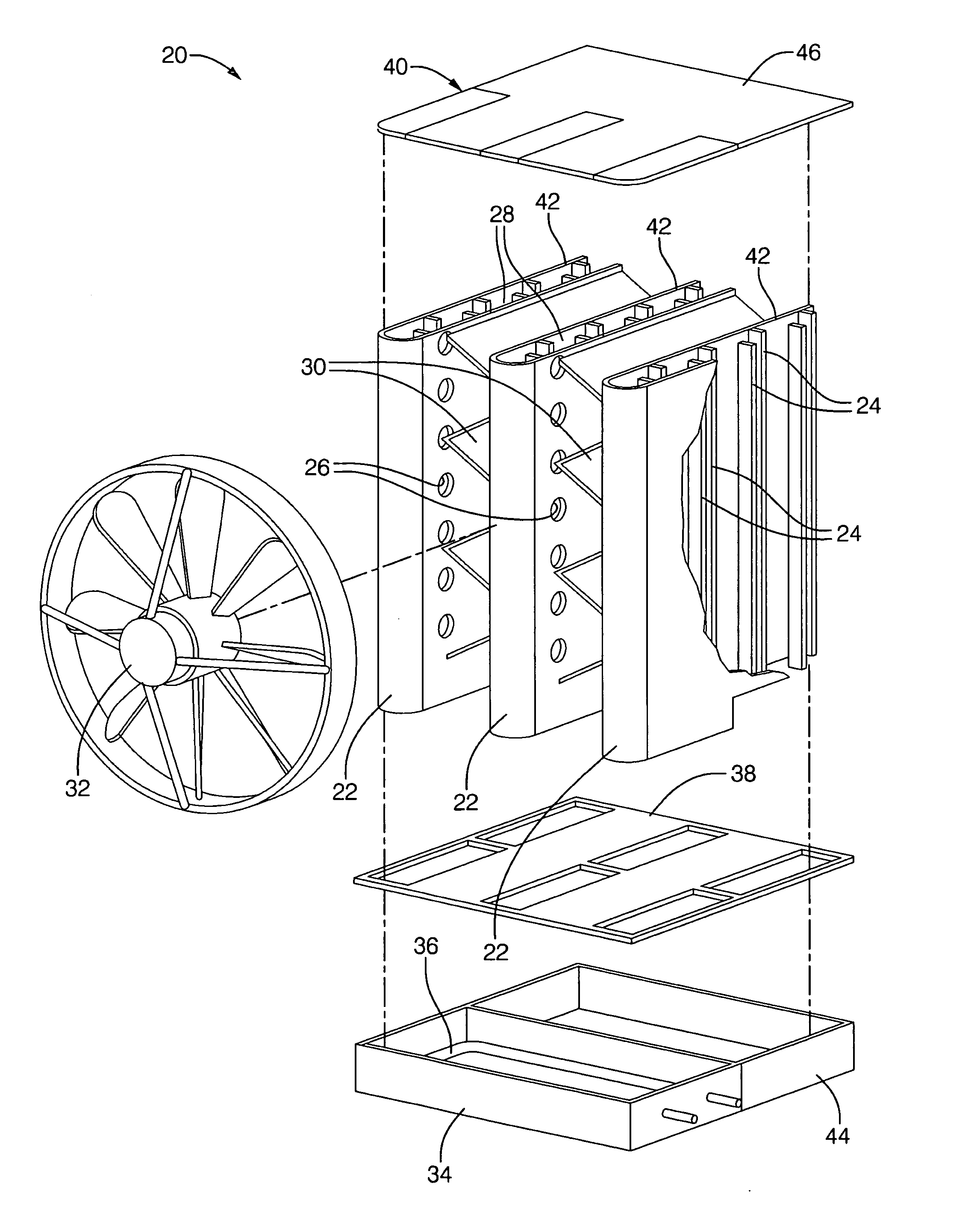
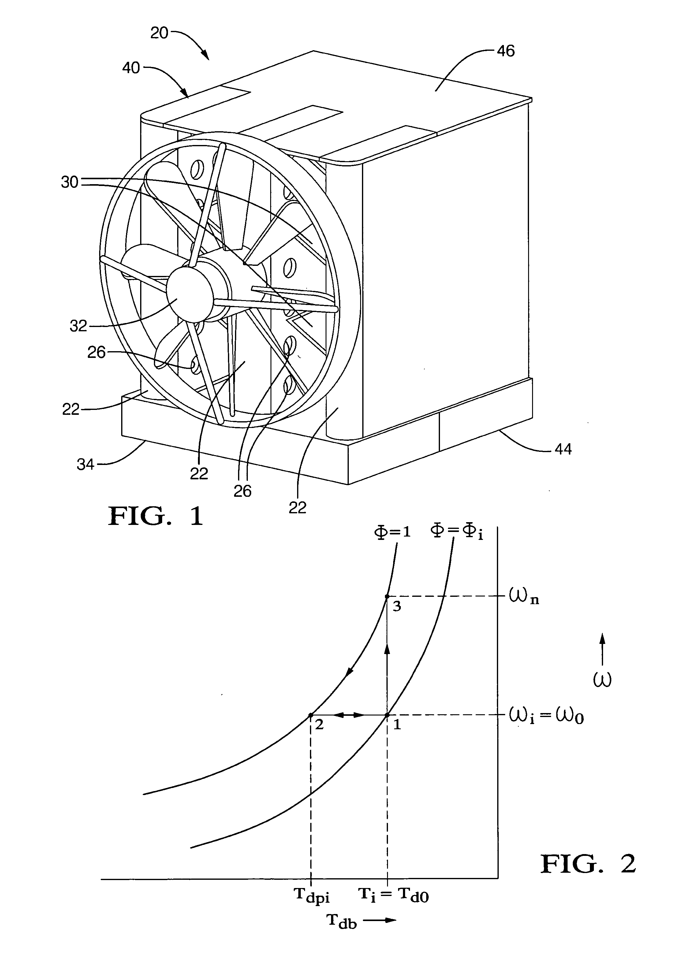
[0017]Referring to the Figures, wherein like numerals indicate corresponding parts throughout the several views, a water desalinating assembly is shown generally at 20. According to a first exemplary embodiment, shown in FIGS. 1 and 3, the assembly 20 includes a plurality of tubes 22 spaced from one another. The tubes 22 extend in a vertical direction from a lower end to an upper end, and in a horizontal direction from a front to a 20 back. A plurality of wet channels is established within the tube 22 walls for carrying a wet airstream, which will be discussed in more detail below. An array of ribs 24 extend inwardly from opposite sides of the tube 22 walls, the ribs 24 running along the height of the tubes 22 from the lower end to the upper end. The ribs 24 are further spaced from one another along the tubes 22 from the front to the back. A bleeder is defined along each tube 22 for receiving 25 air into the wet airstream. According to the first exemplary embodiment, the bleeder com...
PUM
| Property | Measurement | Unit |
|---|---|---|
| Temperature | aaaaa | aaaaa |
| Flow rate | aaaaa | aaaaa |
| Boiling point | aaaaa | aaaaa |
Abstract
Description
Claims
Application Information
 - R&D Engineer
- R&D Manager
- IP Professional
- Industry Leading Data Capabilities
- Powerful AI technology
- Patent DNA Extraction
Browse by: Latest US Patents, China's latest patents, Technical Efficacy Thesaurus, Application Domain, Technology Topic, Popular Technical Reports.
© 2024 PatSnap. All rights reserved.Legal|Privacy policy|Modern Slavery Act Transparency Statement|Sitemap|About US| Contact US: help@patsnap.com