
Container for storing substrate

a container and substrate technology, applied in the field of containers for storing substrates, can solve the problems of increasing the running cost of the fan filter unit, the need for a comparatively high speed of air discharge from the container, etc., and achieve the effect of preventing the dust present inside the container from attaching to the substrate, increasing the speed of clean air discharge, and maintaining the purity of the substrate in the container

Active Publication Date: 2008-03-20
DAIFUKU CO LTD
View PDF9 Cites 11 Cited by
  • Summary
  • Abstract
  • Description
  • Claims
  • Application Information

AI Technical Summary

Benefits of technology

[0006] The present invention has been achieved in view of the above issues, and the object thereof is to provide a container for storing substrates capable of suppressing the running cost of the fan filter unit.
[0011] Accordingly, even when the lid is closed, by performing ventilation with clean air from the opening on the other end side toward the entrance of the container with the fan filter unit, the clean air being discharged from partial openings formed in the entrance, dust present inside the container is prevented from attaching to substrates and also outside air is prevented from entering inside the container, thereby maintaining purity of substrates in the container.
[0012] Also, when the lid is closed, since the container is ventilated with clean air from the opening on the other end side toward the entrance of the container with the fan filter unit, the clean air being discharged from the entrance, the speed of clean air discharged is increased at the entrance as a result of the airflow path being narrowed by the lid. Therefore, even if the ventilation flow rate of the fan filter unit is set comparatively low, the speed of discharged clean air is increased so that outside air is prevented from entering inside the container through the entrance.
[0013] Accordingly, when the lid is closed, since purity of the substrate can be maintained even if the ventilation flow rate of the fan filter unit is set comparatively small, it is possible to reduce the running cost of the fan filter unit by reducing the ventilation flow rate of the fan filter unit.

Problems solved by technology

Therefore in terms of the ventilation flow rate of the fan filter unit, the speed of air discharged from the container needs to be comparatively high, which increases the running cost of the fan filter unit.

Method used


Image

  • Container for storing substrate
  • Container for storing substrate
  • Container for storing substrate

Examples


first embodiment

[0048] The following is a description of preferred embodiments of the present embodiment, with reference to the accompanying drawings.

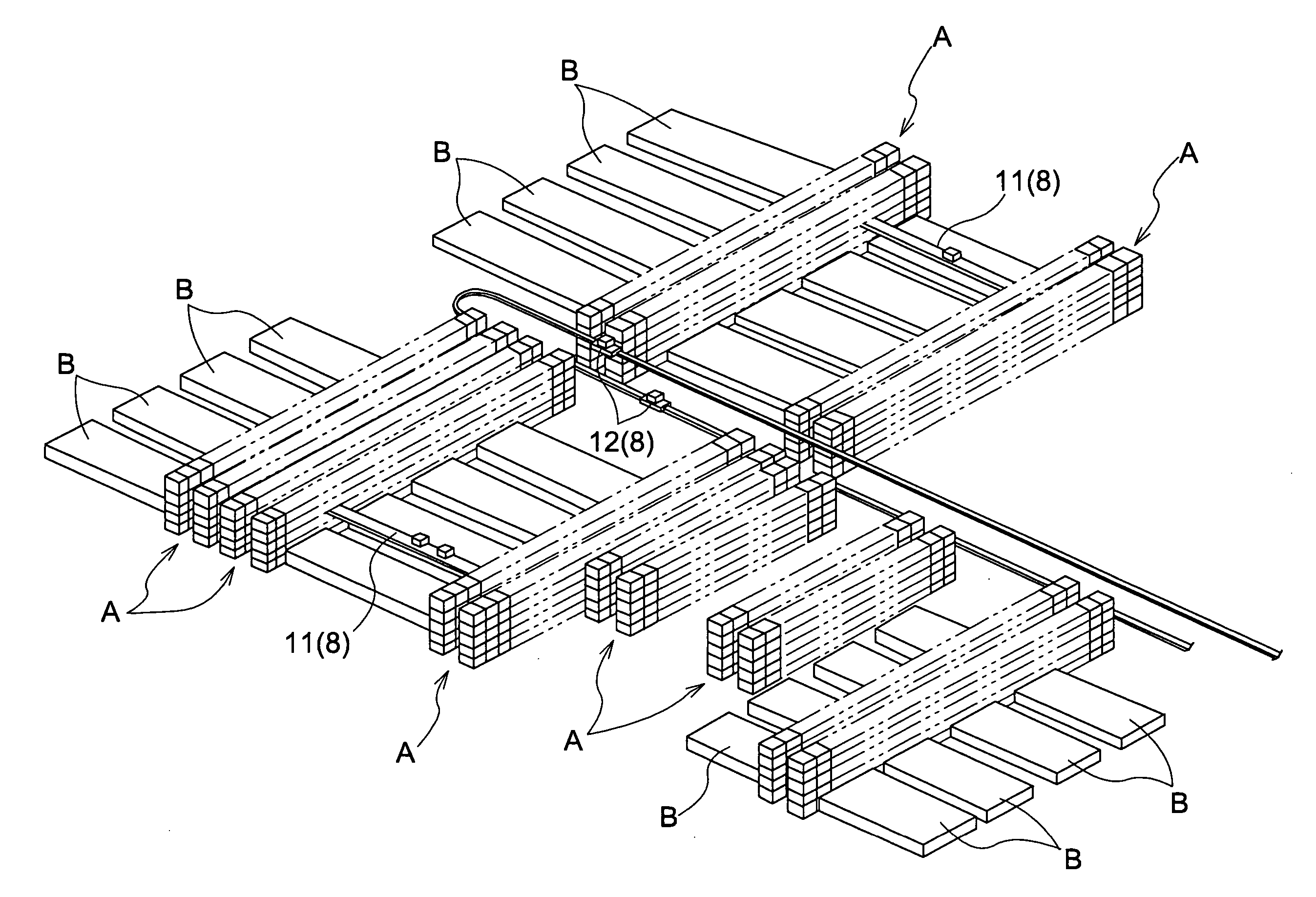
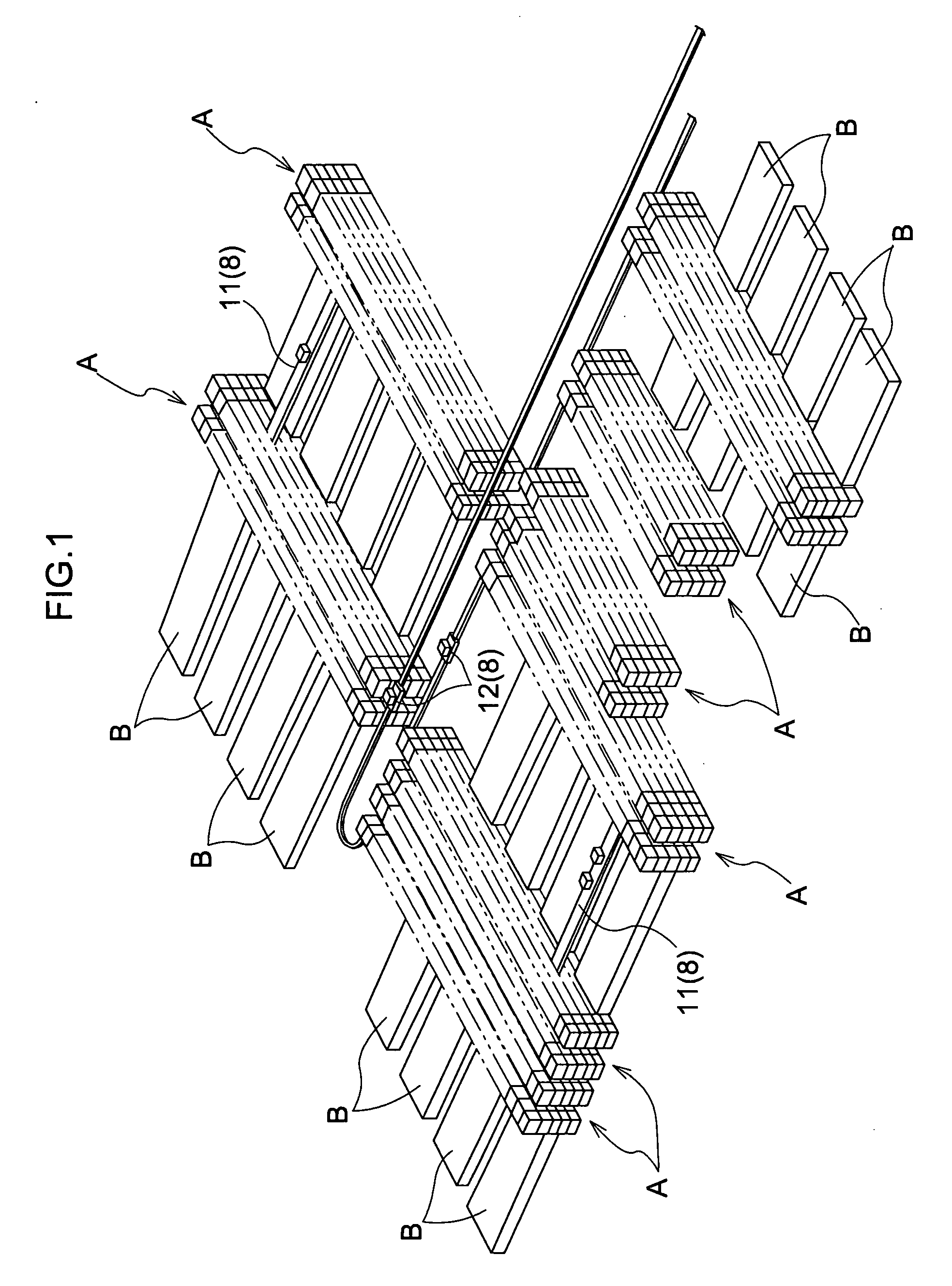
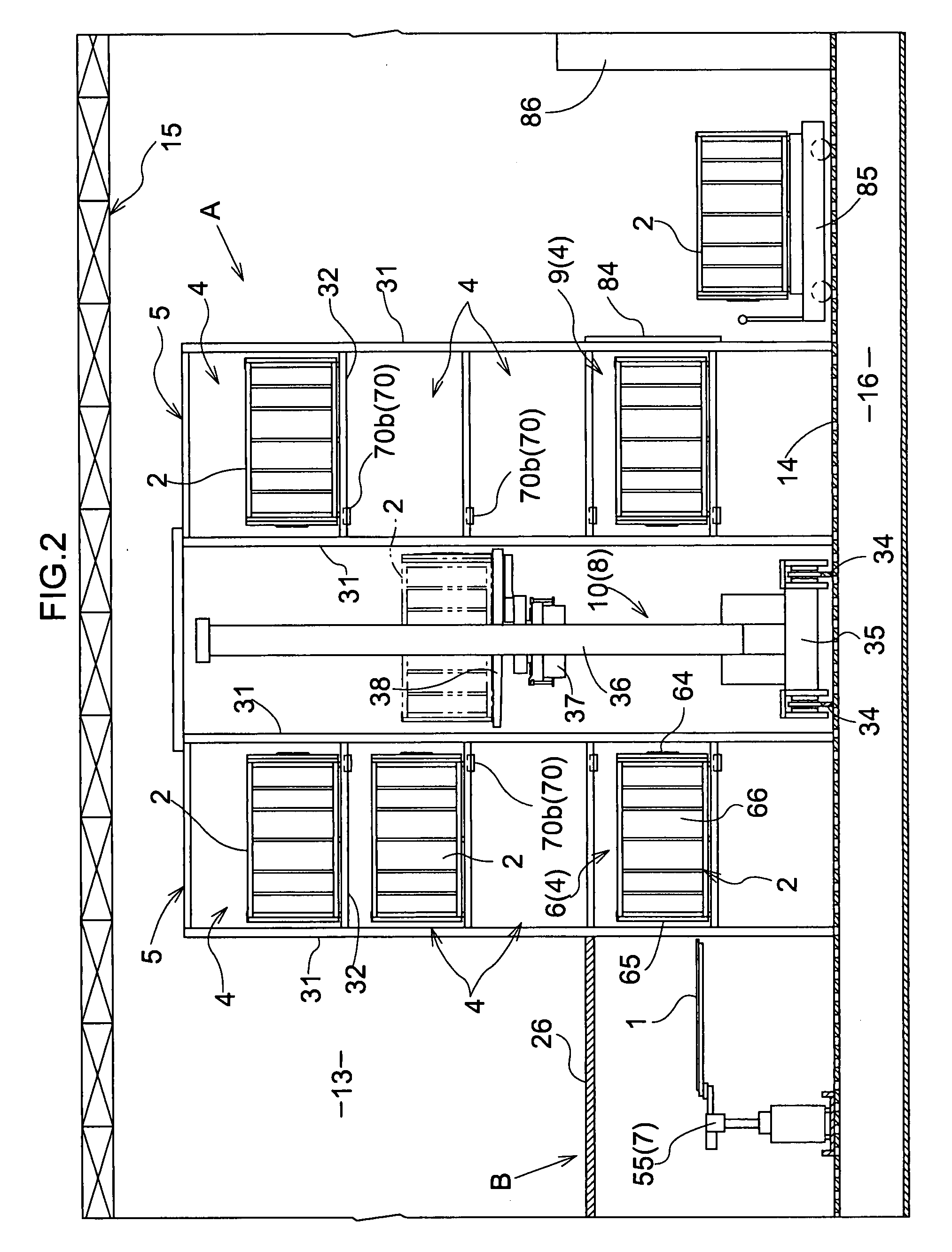
[0049] As shown in FIGS. 2 and 6, substrate processing facility includes a plurality of substrate processing devices 3 that process a substrate 1 having, for example, a rectangular shape, a storage shelf 5 including a plurality of storage sections 4 that store a container 2 that vertically holds a plurality of substrates 1 aligned at certain intervals, a substrate transfer device 7 that takes out the substrates 1 one at a time from the container 2 positioned in a substrate loading / unloading section 6 for each of a plurality of the substrate processing device 3 so as to supply the substrate taken out to the corresponding substrate processing device 3, and store the substrate 1 removed from the substrate processing device 3 into the container 2 positioned in the substrate loading / unloading section 6, and a container transfer device 8 that transfers the...

second embodiment

[0111] This second embodiment is a modified example of the first embodiment, in which the structure for supporting the container 2 in the substrate loading / unloading section 6 and the structure for opening and closing the lid 65 of the container 2 are modified. In the following, the second embodiment of the structure for supporting the container 2 in the substrate loading / unloading section 6 and the structure for opening and closing the lid 65 of the container 2 is described. It should be noted that components configured in a similar manner to those in the first embodiment are assigned the same reference numerals as in the first embodiment, and description thereof is omitted.

[0112] Firstly, the structure for supporting the container 2 in the substrate loading / unloading section 6 is described.

[0113] As shown in FIGS. 23 and 24, at the mount and support section 32 in the substrate loading / unloading section 6, a centering device 111 is provided that moves the container 2 to a correct...


PUM

PropertyMeasurementUnit
areaaaaaaaaaaa
lengthaaaaaaaaaa
longitudinal widthaaaaaaaaaa

Abstract

A container configured to hold a plurality of substrates lined up vertically with space therebetween, which includes a container main unit formed in a tube shape having a quadrangular cross section as a whole that includes a first opening provided on one end side and a second opening provided on the other end side of the container spaced apart in the horizontal direction from the first opening, the first opening serving as an entrance for loading and unloading the substrates, a fan filter unit that is provided in an area of the second opening and that causes movement of air from the second opening toward the first opening, and a lid configured to be attached in an area of the entrance of the container main unit, the lid having an open state and a closed state, and forming a ventilation opening that allows air to pass in the closed state.

Description

BACKGROUND OF THE INVENTION [0001] The present invention relates to a container for storing substrates that vertically holds a plurality of substrates aligned at certain intervals. [0002] Such a container for storing substrates is used for storing substrates such as glass substrates used for liquid display devices or plasma display devices. [0003] In such a container for storing substrates, conventionally, an opening on one end side of a container main unit formed in a tube shape that extends horizontally is configured as an entrance for loading and unloading substrates one at a time, and a fan filter unit, which performs ventilation from an opening on the other end side toward the entrance of the container main unit, is provided at an opening portion on the other end side of the container main unit (for example, see JP 2001-308169A). [0004] In the above-described container for storing substrates, by performing ventilation with clean air (or filtered air) from an opening on the othe...

Claims


Application Information

Patent Timeline
Patent Type & Authority Applications(United States)
IPC IPC(8): B65D85/90
CPCB65D85/48B65G49/061B65G49/067B65G2249/02H01L21/67775H01L21/6734H01L21/67363H01L21/67393H01L21/67769H01L21/67017H01L21/67
Inventor IKEHATA, YOSHITERU
Owner DAIFUKU CO LTD
Learn More