
Image pickup device having quickview display function

Inactive Publication Date: 2008-03-20
CASIO COMPUTER CO LTD
View PDF17 Cites 11 Cited by
  • Summary
  • Abstract
  • Description
  • Claims
  • Application Information

AI Technical Summary

Benefits of technology

[0010]In another aspect of the present invention there is provided an image display control program (recorded on a recording medium) for causing a computer to perform certain functions, the computer contained in an image pickup device comprising: a display unit; an acquisition unit for acquiring a consecutive plurality of object images by consecutively photographing an object according to a predetermined frame rate in response to photographic operations; and a recording unit for recording the

Problems solved by technology

This behavior can cause the user to lose the next photographic opportunity and hinder a photographic shoot.
However, by canceling this display the user can only partially confirm the contents of the last shot, and is thus forced to take the next shot while being unsure about the last shot.
However, given that the display screen provided on the image pickup device has a limitation in size, as the number of consecutive images increases, the display size of each image displayed in the multi-screen becomes relatively smaller, thus making it difficult to confirm the contents of the shot.

Method used


Image

  • Image pickup device having quickview display function
  • Image pickup device having quickview display function
  • Image pickup device having quickview display function

Examples


first embodiment

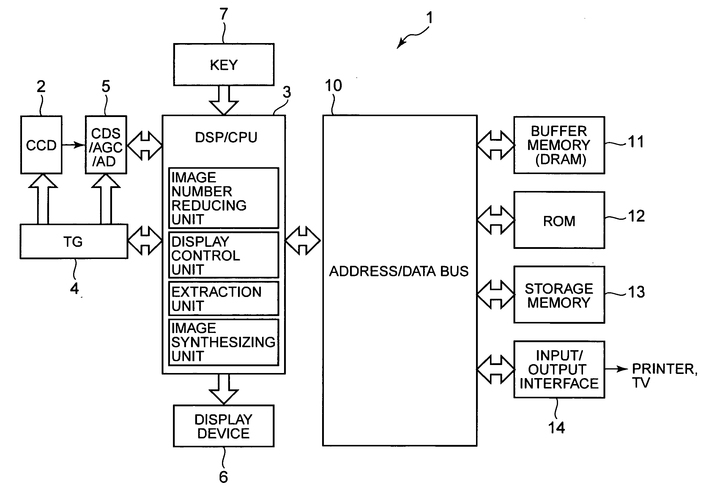
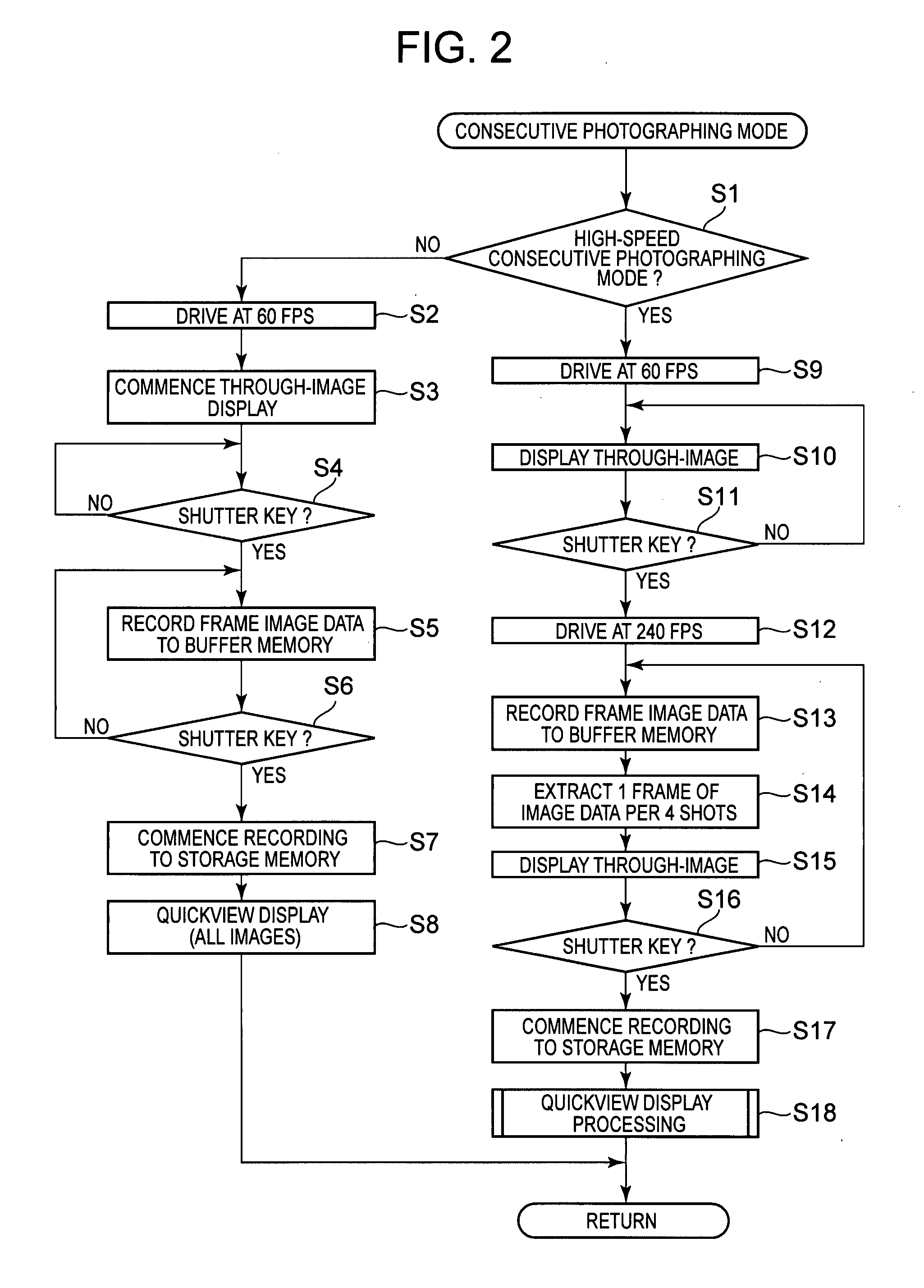
[0037]FIG. 3 is a flowchart showing the processing procedure of the quickview processing (step S18) in the present invention. A counter N in the DSP / CPU 3 is set to an initial value 1 (step S101), and another counter L is set to 4 times of the value of counter N (step S102). Additionally, the Lth frame of image data among the above-described frame data is extracted from the buffer memory 11 (or alternatively the storage memory 13) (step S103), and an image based on this extracted image data is displayed by the display device 6 (step S104). This image display is maintained until a predetermined time (for example, 1 second) has passed (step S105). If the predetermined time has passed (step S105; YES), it is determined whether or not (L≧Nmax−3), in other words, when the processing is conducted to set (L=N×4) in the next step S102, it is determined whether or not L will exceed the total number of image data frames (Nmax) in the above-described frame data (step S106). Additionally, until...

second embodiment

[0041]FIG. 5 is a flowchart showing the processing procedure of the quickview display processing (step S18) in the present invention. A first frame of image data among the above-described frame data is read from the buffer memory 11 (or alternatively the storage memory 13) (step S201), and furthermore, the next (initially, the second) frame of image data is also read (step S202). Subsequently, the images of the image data read in step S201 (or alternatively the image data read in the previous iteration of step S202) and the next image data read in step S202 are compared (step S203), and it is determined whether or not the difference (change) between the two images meets or exceeds a set value (step S204). If the difference between the two images does not meet the set value, i.e., in the case where the change between adjacent images in the consecutive frame data is small (step S204; NO), the process proceeds to step S207 without conducting the processing in steps S205 and S206.

[0042]...

third embodiment

[0044]FIG. 6 is a flowchart showing the processing procedure of the quickview display processing (step S18) in the present invention. A counter N in the DSP / CPU 3 is set to an initial value of 1 (step S301), and frames of image data (a, b, c, d), corresponding to the ordinals (N˜N+3) as indicated by this counter N, are read from the above-described frame data (step S302). Subsequently, by calculating (L=[a+b+c+d] / 4), (N˜N+3) frames of image data (i.e., 4 frames) are synthesized at a weight of ¼, thereby creating a single frame of synthesized image data L (step S303). Subsequently, an image based on the synthesized image data L is displayed by the display device 6 (step S304). This image display is maintained until a predetermined time (for example, 1 second) has passed (step S305). If the predetermined time has passed (step S305; YES), it is determined whether or not (N+4>Nmax); in other words, when the processing is conducted to set (N=N+4) in the next iteration of step S307, it is...


PUM


Abstract

In quickview display processing, a counter N is set to an initial value of 1, and a counter L is set to 4 times the counter N. Then, from a storage memory, the Lth frame of image data in frame data recorded by high-speed consecutive photographing is extracted, and an image based on this extracted image data is displayed by a display device. Consequently, by iteratively executing the processing according to this flowchart, the fourth, eighth, twelfth, etc., frames of image data are read from the frame data, and as a result of the displaying of the extracted image and passage of a redetermined time, images based on these read image data, being every fourth frame of the frame data, are displayed at a predetermined time interval by the display device.

Description

BACKGROUND OF THE INVENTION[0001]1. Field of the Invention[0002]The present invention relates to image pickup devices and image display control methods, implementable in digital cameras, provided with a function for displaying a photographed image immediately after the photographing thereof (to be referred to hereinafter as “quickview display”).[0003]2. Description of the Related Art[0004]Image pickup devices having quickview display functions are conventionally known. These image pickup devices activate the quickview display immediately after a consecutive photographing, and thereby display a plurality of images acquired by the consecutive photographing either in succession, or alternatively on a multi-screen display. Consequently, as a result of the user viewing the quickview display, the user is able to confirm the photographed contents of the consecutive photographing, and is able to subsequently conduct the next shoot (for example, refer to Japanese Unexamined Patent Applicatio...

Claims


Application Information

Patent Timeline
IPC IPC(8): H04N5/225
CPCH04N5/23293H04N23/63H04N23/00
Inventor YUYAMA, MASAMI
Owner CASIO COMPUTER CO LTD
Learn More