Gear shift control device for a hybrid electric vehicle

a hybrid electric vehicle and gear control technology, applied in the direction of engine-driven generators, dynamo-electric gear control, transportation and packaging, etc., can solve the problems of prolonging the time for the gear, the electric motor cannot be operated, and the electric motor cannot be synchronized at the revolution speed

Inactive Publication Date: 2008-03-20
MITSUBISHI FUSO TRUCK AND BUS CORPORATION
View PDF7 Cites 44 Cited by
  • Summary
  • Abstract
  • Description
  • Claims
  • Application Information

AI Technical Summary

Benefits of technology

[0013]An aspect of the present invention is directed to a gear shift control device for a hybrid electric vehicle capable of transmitting both of a driving force outputted from an engine and a driving force outputted from an electric motor to driving wheels, comprising a transmission unit having a plurality of gears and a synchronizing mechanism, the transmission unit being capable of switching between a mode for transmitting a driving force to the driving wheels through a gear selected from the gears and a neutral mode for blocking the transmission of the driving

Problems solved by technology

In this parallel hybrid electric vehicle, there is the possibility that the electric motor cannot be operated for some reason, for example, in case that a battery for supplying power to the electric motor is in a over-discharged state or that there is a fault in an inverter circuit for controlling the operation of the electric motor.
However, if the electric motor becomes inoperable for some reason, the revolution speed synchronization control of the electric motor cannot

Method used


Image

  • Gear shift control device for a hybrid electric vehicle
  • Gear shift control device for a hybrid electric vehicle
  • Gear shift control device for a hybrid electric vehicle

Examples


Embodiment Construction

[0019]One embodiment of the present invention will be described below with reference to the attached drawings.

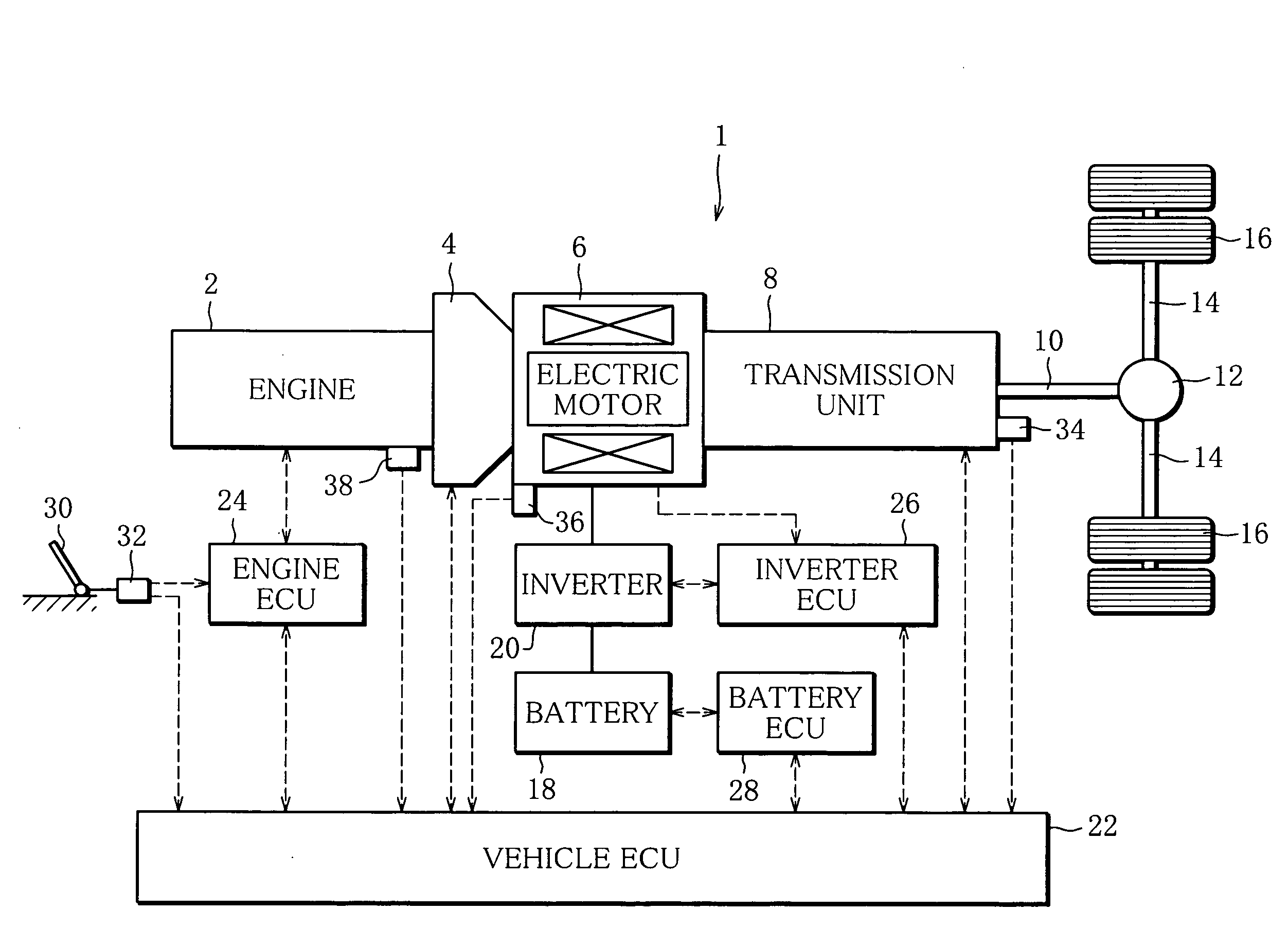
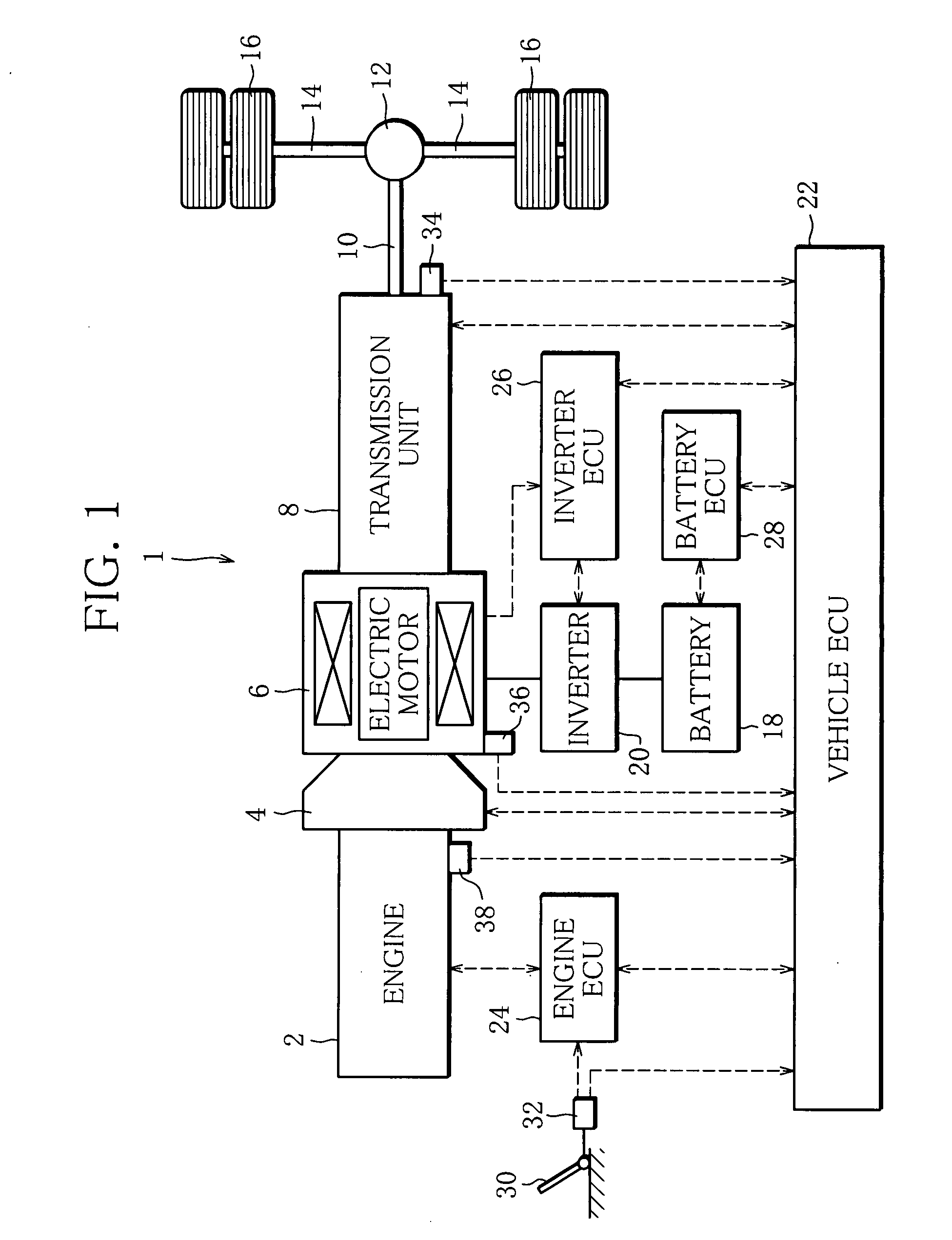
[0020]FIG. 1 is a diagram showing the schematic structure of a hybrid electric vehicle 1 to which the present invention is applied.

[0021]An input shaft of a clutch 4 is coupled to an output shaft of an engine 2, which is a diesel engine. An output shaft of the clutch 4 is coupled to an input shaft of an automatic transmission unit (hereinafter, referred to as transmission unit) 8 through a rotary shaft of a permanent-magnetic synchronous motor (hereinafter, referred to as electric motor) 6.

[0022]In the transmission unit 8, a speed-change gear mechanism, not shown, is installed, which includes a plurality of gears in between the input and output shafts. The transmission unit 8 can be selectively switched between a neutral mode that selects none of the gears and a mode that selects any one of the gears. The transmission unit 8 is so constructed that the gears are shifted while...


PUM


Abstract

A hybrid electric vehicle is capable of transmitting both of a driving force outputted from an engine and a driving force outputted from an electric motor and blocking the transmission of the driving force from the engine to a transmission unit by using a clutch. If the electric motor is in an inoperable state when a gear currently used in the transmission is shifted to a target gear, after disengaging the clutch and bringing the transmission unit into a neutral mode, the vehicle ECU implements temporary engagement control for temporarily engaging and then disengaging the clutch, selects the target gear, and then engages the clutch again.

Description

BACKGROUND OF THE INVENTION[0001]1. Field of the Invention[0002]The present invention relates to a gear shift control device for a hybrid electric vehicle, and more specifically to a gear shift control device for a hybrid electric vehicle capable of transmitting a driving force of an engine and a driving force of an electric motor to driving wheels.[0003]2. Description of the Related Art[0004]A parallel hybrid electric vehicle has conventionally been developed and in practical use, which is designed to transmit the driving forces outputted from the engine and the electric motor to the driving wheels.[0005]One of such parallel hybrid electric vehicles is a hybrid electric vehicle in which there is provided a clutch capable of blocking the transmission of the driving force from the engine to the automatic transmission unit, and in which the rotary shaft of the electric motor is coupled to between the output shaft of the clutch and the input shaft of the automatic transmission.[0006]Wh...

Claims


Application Information

Patent Timeline
IPC IPC(8): B60W10/10B60K6/48B60K6/547B60L50/16B60W10/02B60W20/00F16D48/02F16H59/40F16H59/42F16H59/46F16H61/02F16H61/68F16H61/682F16H63/46
CPCB60K6/48Y10T477/33B60L2240/425B60L2240/441B60L2240/486B60W10/02B60W10/06B60W10/08B60W10/11B60W20/00B60W30/19B60W2510/0216B60W2510/0638B60W2510/087B60W2510/104B60W2510/244F16H61/0403F16H2306/48Y02T10/6221Y02T10/6286Y02T10/642B60K6/547Y02T10/62Y02T10/64B60W20/30B60W2510/0208B60W10/10
Inventor OGATA, MAKOTO
Owner MITSUBISHI FUSO TRUCK AND BUS CORPORATION
Why Eureka
Try Eureka