Device for Manipulating and Supplying Hollow or Intervertebral or Disk Prosthesis With Flowable Osteocementum

Inactive Publication Date: 2008-03-20
DEPUY SYNTHES PROD INC
View PDF20 Cites 60 Cited by
  • Summary
  • Abstract
  • Description
  • Claims
  • Application Information

AI Technical Summary

Benefits of technology

[0016] For a further embodiment, the handle is mounted in one piece at the front end of the tube. Preferably, the rear end of the tube has a terminal expansion, which permits an axial rotation of the in

Problems solved by technology

If the osteocementum must flow over an excessively long path (very long tube plus handle), the d

Method used


Image

  • Device for Manipulating and Supplying Hollow or Intervertebral or Disk Prosthesis With Flowable Osteocementum
  • Device for Manipulating and Supplying Hollow or Intervertebral or Disk Prosthesis With Flowable Osteocementum
  • Device for Manipulating and Supplying Hollow or Intervertebral or Disk Prosthesis With Flowable Osteocementum

Examples


Embodiment Construction

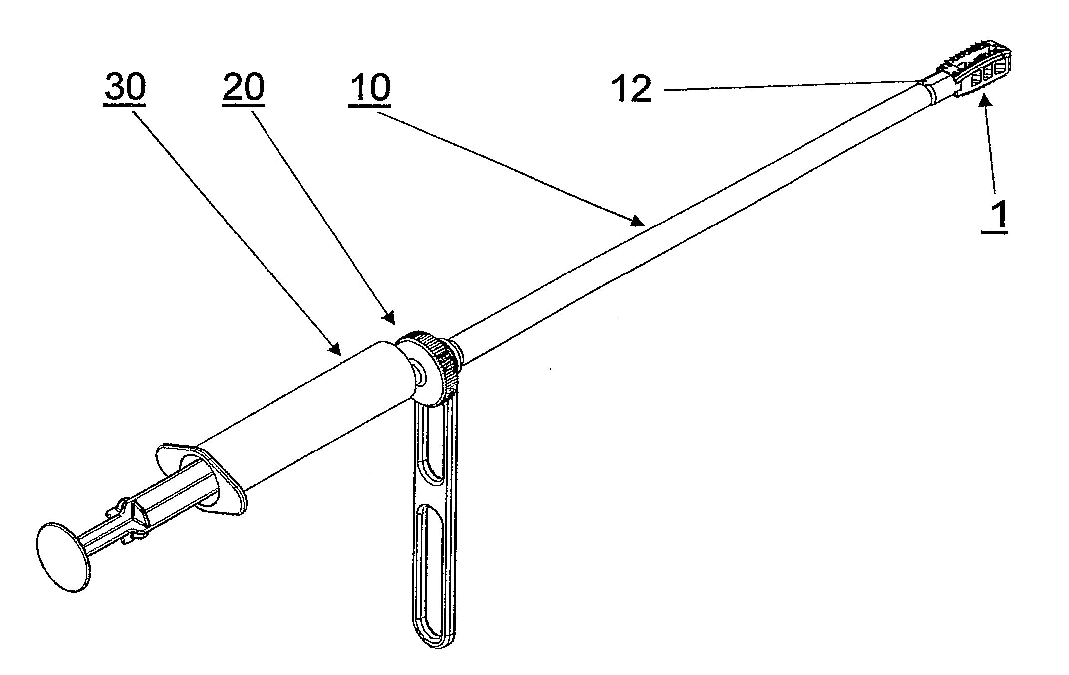
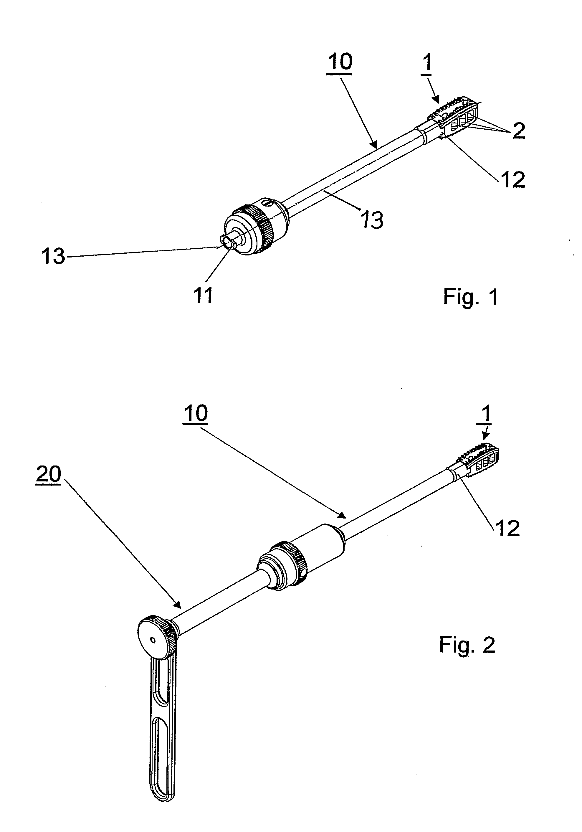
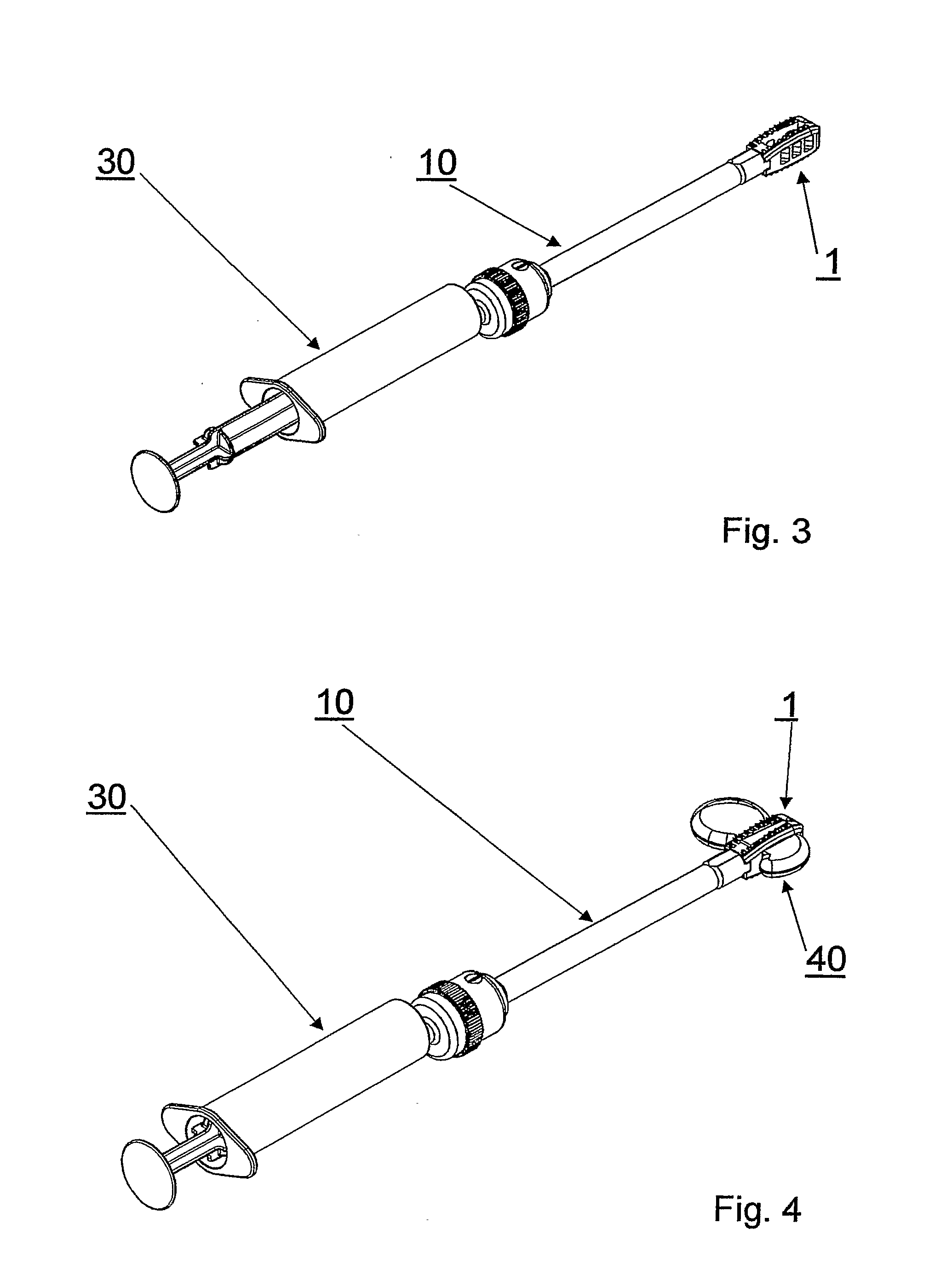
[0026] The device for manipulating and supplying hollow intervertebral and disk prostheses 1 with a flowable hydraulic osteocementum, shown in FIGS. 1-4, comprises a tube 10 with a front end 11 and a rear end 12, the latter being connected tightly to a hollow, perforated intervertebral prosthesis 1. A handle 20 is coupled to the front end 11 of the tube 10, as shown in FIG. 2. With this handle 20, it is possible to manipulate the intervertebral prosthesis 1 over the tube 10, which is fastened to the intervertebral prosthesis 1. After the intervertebral prosthesis 1 has been positioned in the intervertebral space, the handle 20 is removed and, as shown in FIG. 3, replaced by a conveying unit for the flowable osteocementum 30. The conveying unit for flowable osteocementum 30 may consist of an osteocementum syringe, which is customarily used for this purpose.

[0027] The front end 11 of the tube 10 is constructed in such a manner that, alternatively, the handle 20 or the osteocementum s...


PUM


Abstract

A manipulation device of hollow intervertebral or disk prostheses and to the supply thereof with a flowable, hydraulic, osteocementum. Said device comprises a tube provided with a front end and a rear end, a handle and a guiding element for the flowable osteocementum. The front end of the tube is embodied in such a manner that the handle or the guiding element for the flowable osteocementum can be coupled thereto. The rear end of the tube is embodied in such a manner that it can be connected in a rotationally fixed and sealed manner to a hollow intervertebral or disk prosthesis. The handle can be connected in a rotationally fixed manner to the tube and the tube is torsionally fixed in relation to the longitudinal axis thereof.

Description

FIELD OF THE INVENTION [0001] The invention relates to an intervertebral prosthesis or disk prosthesis, especially for arthrodesis surgery by means of dorsal access PLIF (posterior lumbar interbody fusion), TLIF (transforaminal lumbar interbody fusion), ELIF (extraforaminal lumbar interbody fusion), ALIF (anterior lumbar interbody fusion) and ACIF (anterior cervical interbody fusion. The objective of this surgical technique is the treatment of a degenerated or otherwise diseased intervertebral disk. The surgeon looks for access to the intervertebral disk through a centrally placed skin incision. Subsequently, he exposes the rear region of the movement segments, especially the laminae and the pedicle entry points. By means of a partial resection of the facettal and laminar components, the surgeon aims past the nerve roots and the medullary space in the direction of the diseased intervertebral disk. BACKGROUND OF THE INVENTION [0002] For this surgical technique, only a limited amount ...

Claims


Application Information

Patent Timeline
IPC IPC(8): A61B17/58A61F2/00A61F2/44A61F2/46
CPCA61B17/7098A61F2/4455A61F2/4601A61F2/4611A61F2002/30235A61F2310/00353A61F2002/4475A61F2002/4624A61F2002/4627A61F2002/4635A61F2230/0069A61F2002/30785A61F2/4603A61F2002/30593
Inventor LECHMANN, BEATFRIGG, ROBERTBUERKI, ROGER
Owner DEPUY SYNTHES PROD INC
Why Eureka
Try Eureka