Vehicle exhaust component assembly using magnetic pulse welding

a technology of exhaust components and magnetic pulse welding, which is applied in the direction of machines/engines, manufacturing tools, other domestic articles, etc., can solve the problems of environmental cleanup, potential physical interface problems between the head of the welding device,

Inactive Publication Date: 2008-03-27
AUTOMOTIVE COMPONENTS HOLDINGS
View PDF8 Cites 13 Cited by
  • Summary
  • Abstract
  • Description
  • Claims
  • Application Information

AI Technical Summary

Benefits of technology

[0008]The present invention provides a method for joining two members of an exhaust system to one another utilizing a magnetic pulse welding operation. An interference condition created by a flared secti...

Problems solved by technology

For example, there is a potential physical interface issue between the head of welding device and the head of a bolt (for fastening a flange member to respective exhaust member) when fastening the ...

Method used


Image

  • Vehicle exhaust component assembly using magnetic pulse welding
  • Vehicle exhaust component assembly using magnetic pulse welding
  • Vehicle exhaust component assembly using magnetic pulse welding

Examples


Embodiment Construction

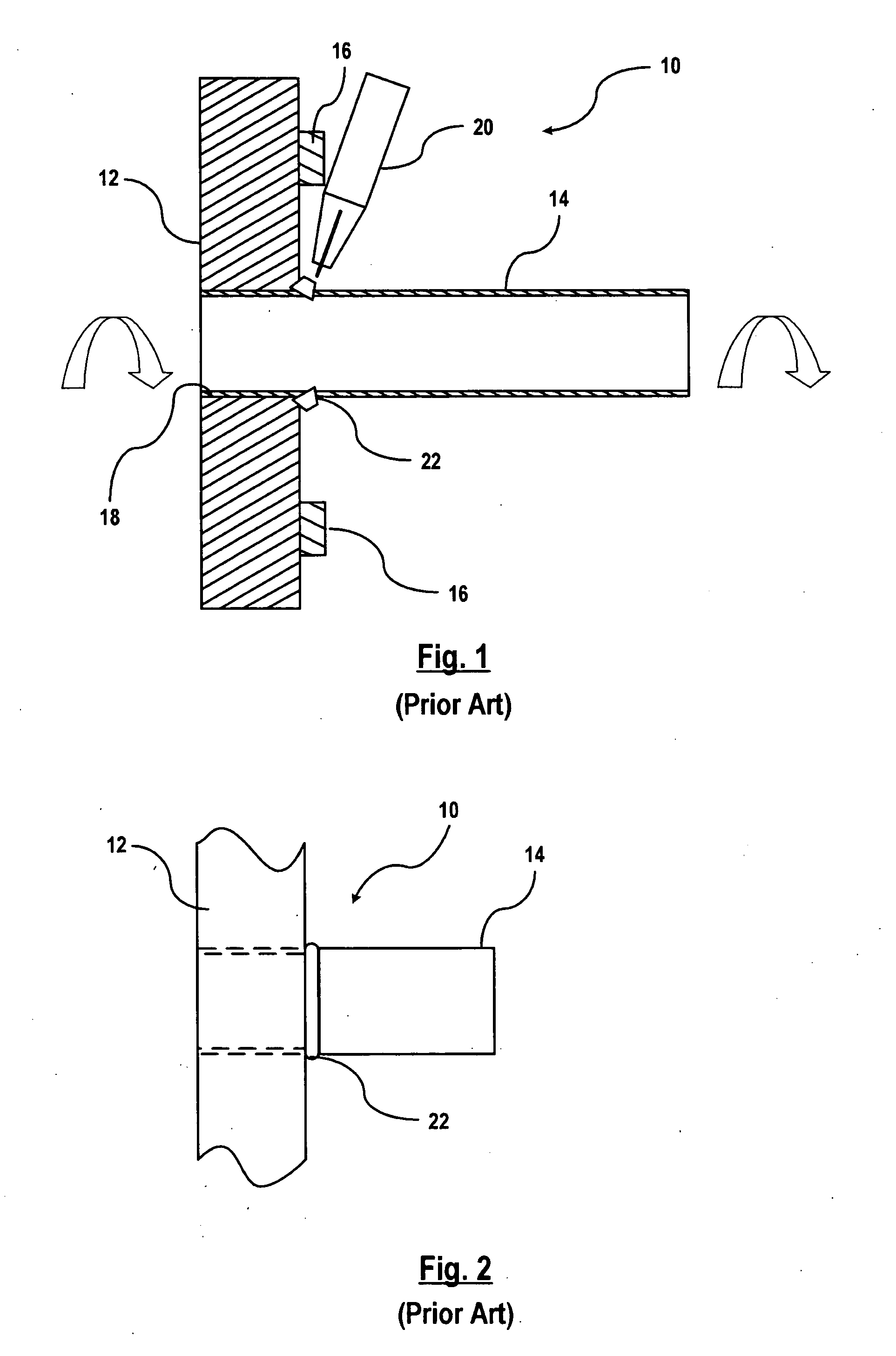
[0026]FIGS. 1 and 2 show a cross-section view and a side view, respectively, of exhaust system components coupled to one another by a prior art weld operation. An illustration of a pair of exhaust members, such as a pipe assembly exhaust converter outlet, is shown generally at 10. The pair of coupled exhaust members 10 includes a flange member 12 and a pipe member 14.

[0027]The flange member 12 includes a plurality of bolts 16 that are used to couple the flange member 12 to a third exhaust member (not shown). The pipe member 14 is secured to the flange member 12 by inserting the pipe member 14 within receiving section 18 (i.e., bore) of the flange member 12 to form a pre-assembly and then welded together at an adjoining location. The flange member 12 and pipe member 14 are welded together utilizing a TIG welding technique or a MIG welding technique. To weld the pre-assembly together using prior art methods, the pre-assembly is secured within a fixture and (not shown) rotated while a ...


PUM

PropertyMeasurementUnit
Diameteraaaaaaaaaa

Abstract

A vehicle exhaust system is provided that includes a first exhaust member having an end that includes an enlarged section. A second exhaust member is sized to receive a portion of the first exhaust member. The enlarged section of the first exhaust member has an outer diameter that is larger than an inner diameter of at least one section of the second exhaust member for creating an interference condition between the first and second exhaust member to prevent axial movement of the first exhaust member in at least one axial direction. The first exhaust member is secured to the second exhaust member by magnetic pulse welding.

Description

CROSS-REFERENCE TO RELATED APPLICATIONS[0001]Not ApplicableSTATEMENT REGARDING FEDERALLY SPONSORED RESEARCH OR DEVELOPMENT[0002]Not ApplicableREFERENCE TO A SEQUENCE LISTING, A TABLE, OR A COMPUTER PROGRAM LISTING COMPACT DISC APPENDIX[0003]Not ApplicableBACKGROUND OF THE INVENTION[0004]1. Field of the Invention[0005]This invention relates in general to a vehicle exhaust system, and more specifically, to permanently affixing the vehicle exhaust system components using magnetic pulse welding.[0006]2. Background of Related Art[0007]Exhaust systems typically include a plurality of exhaust members that are joined to one another by metal inert gas (MIG) or tungsten inert gas (TIG) welding. The coupling of exhaust members together requires that the coupled joints be leak-proof. Traditional MIG and TIG welding methods present several disadvantages. For example, there is a potential physical interface issue between the head of welding device and the head of a bolt (for fastening a flange me...

Claims


Application Information

Patent Timeline
IPC IPC(8): F01N7/00F01N7/10F01N13/10
CPCF01N13/1805B23K9/0286B23K9/167B23K9/173B23K20/06Y10T29/49803B23K2201/06B23K2203/02Y10T29/49345Y10T29/49398Y10T29/49968B23K2201/006B23K2101/006B23K2101/06B23K2103/02
Inventor CAI, HAIMIANCHEN, BAOLUOWANG, HUISCHOENBORN, ROBERT
Owner AUTOMOTIVE COMPONENTS HOLDINGS
Why Eureka
Try Eureka