Apparatus for controlling slip deployment in a downhole device

a technology for packing devices and slip extensions, which is applied in the direction of sealing/packing, fluid removal, borehole/well accessories, etc., can solve the problems of one piece segmented assembly being used in applications with high expansion ratio, failure of the packer to anchor and seal, and inability to ensure the symmetry around the circumference of the packing device is maintained, etc., to achieve the effect of increasing the expansion ratio of the plug, increasing the expansion ratio, and saving the cost of production

Active Publication Date: 2008-03-27
COOK ROBERT BRADLEY +1
View PDF4 Cites 46 Cited by
  • Summary
  • Abstract
  • Description
  • Claims
  • Application Information

AI Technical Summary

Benefits of technology

[0017]An advantage of the present disclosure is that the downhole tool can be efficiently and economically manufactured. Another advantage is the slip design utilizes a one-piece cast iron construction, although it is within the teachings of the present disclosure that the slips may already be segmented. Each segment that is created by the fracturing of the slip against the cone and is accomplished by the placement of cuts or reduced wall areas in uniform manner around the circumference of the slip. Yet another advantage is that alignment shear pins are placed in the slip, and wherein the shear pins extend from the plug body into the slip body (one shear pin per segment) to keep the slip segments in place (aligned) relative to the inner mandrel and cone until the extension is required.
[0018]Another advantage is that the compression of the cone into the internal portion of the slip causes the slip to ride up the angle of the cone and the force generated causes the one-piece slip to fracture into segments. Each segment is then held in relative alignment by the alignment shear pin. Further compression moves the cone further into the slip body causing further expansion until the slip reaches the proposed setting internal diameter.
[0019]A feature of the present invention is the tapered end of the slip. The teeth that cause the slips to bite into the wall of the tubular do not come into contact with the tubular inner portion until a minimum diameter is reached. This feature is advantageous when running through a small tubular to get to the intended setting area of larger diameter. Emergency removal of a plug in an inner portion too small for the slip to engage is easily accomplished when the slips are not anchored to the tubular.
[0020]Another feature is that the tapered end also allows for higher expansion ratios for the plug i.e. the tool outer diameter before being set versus the tool outer diameter after being set. The final setting diameter can be a much higher ratio relative to the plug running diameter than with the prior art packers. The higher expansion ratio is further assisted by the presence of a radius lower end (i.e. curved end) of the slip that allows the slip to deploy in a rocker fashion rather than sliding, as done in the prior art, from one outer diameter to the next outer diameter.

Problems solved by technology

Various problems are encountered with the prior art in deployment of prior art slips, some of which may lead to a failure of the packer to anchor and seal.
As those of ordinary skill in the art will recognize, a potential problem with the prior art arrangement is that not all segments must fracture for the slip to deploy and there is no assurance that any symmetrical spacing around the circumference of the packing device is maintained.
This problem is made worse in the actual setting dynamic by the sudden movement (relief) that takes place when the slip which is subjected to the force required to break the segments is no longer retained on the plug mandrel, in a sense, the slip segments accelerate away from the mandrel independent of the movement of the cone.
Thus, this problem prevents the one piece segmented assembly from being used in applications with high expansion ratio over the original diameter of the un-segmented slip.
This creates friction / drag that must be overcome by force from the setting tool.
Excessive drag may cause release of the plug from the setting tool before optimum compression of the elastomer is achieved thus possibly reducing the effectiveness of the elastomer seal.

Method used


Image

  • Apparatus for controlling slip deployment in a downhole device
  • Apparatus for controlling slip deployment in a downhole device
  • Apparatus for controlling slip deployment in a downhole device

Examples


Embodiment Construction

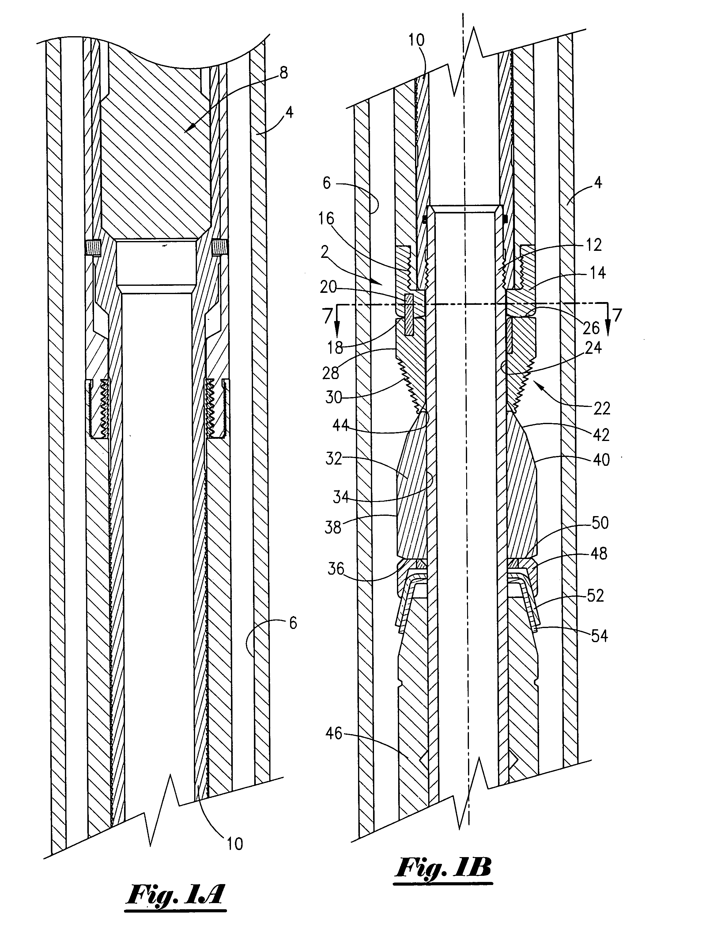
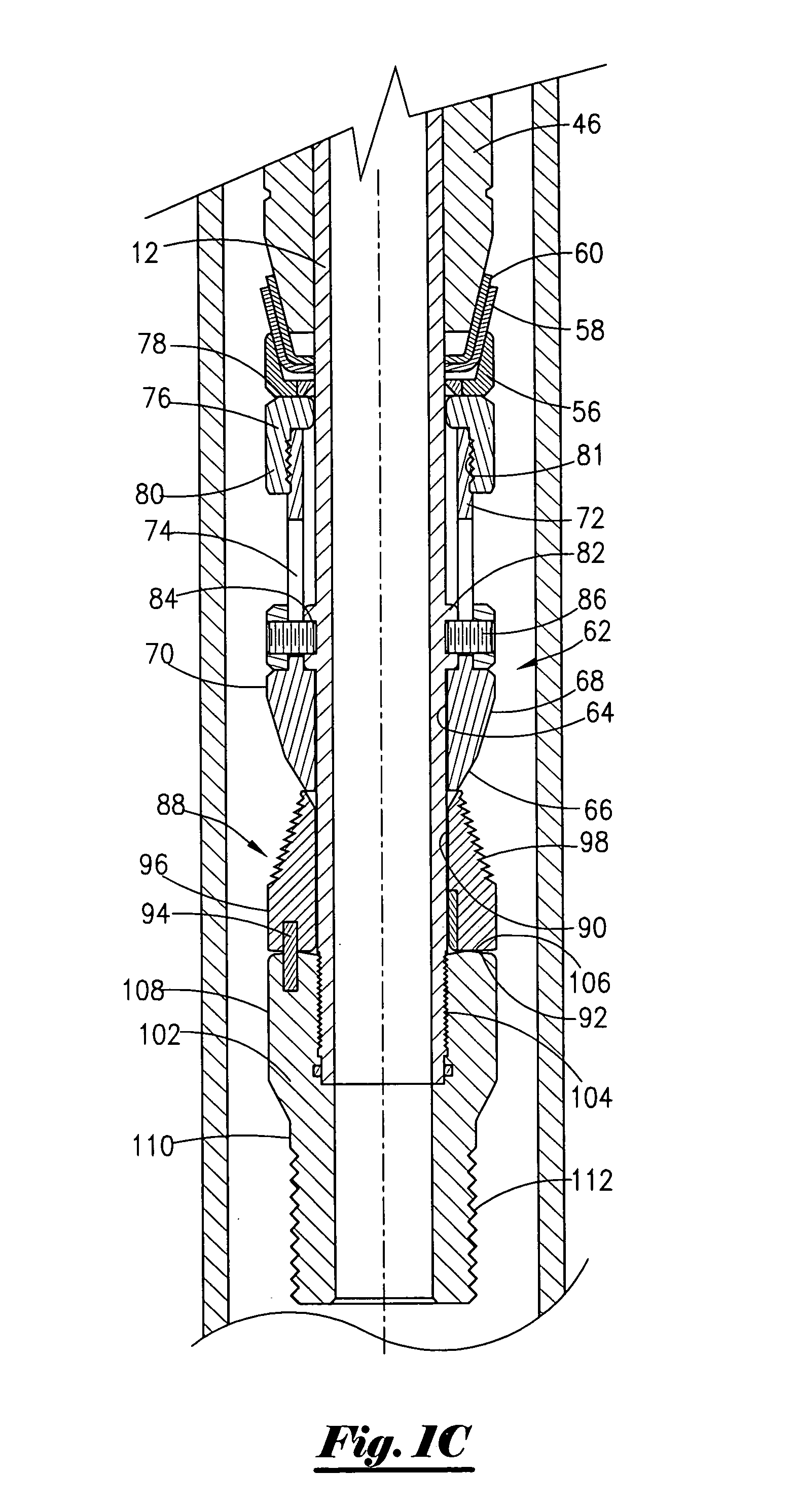
[0034]Referring now to FIGS. 1A, 1B, and 1C, the most preferred embodiment of the present invention in the run-in mode will now be described. More specifically, the apparatus 2 is shown disposed within a well 4, and wherein the well 4 may be referred to as a casing string 4. The well 4 has an inner diameter portion 6. As those of ordinary skill in the art will recognize, the apparatus 2 is operatively associated with a setting tool means 8 for setting the apparatus 2. Setting tool means may be hydraulically activated, mechanically activated, explosively activated, or electrically activated. In the most preferred embodiment, the setting tool means 8 used with the apparatus 2 will be electrically activated. Setting tool means of this type are commercially available from Owen Oil Tools Inc. under the name Wireline Pressure Setting Tool.

[0035]The setting tool means 8 is operatively attached with a power mandrel 10 that is threadedly attached to the inner mandrel 12 of the apparatus 2. T...


PUM


Abstract

An apparatus for use in a well. The apparatus comprises a mandrel containing a radial shoulder, a sub member concentrically disposed about the mandrel, and an upper slip, concentrically disposed about the mandrel, for engaging the well. The apparatus further comprises an upper cone abutting an underside of the upper slip, and wherein the upper cone is disposed about the mandrel, and an elastomer operatively associated with the upper cone, and wherein the elastomer is disposed about the mandrel. The apparatus further includes a lower slip, concentrically disposed about the mandrel, for engaging with the internal portion of the well, and lower cone abutting an underside of the lower slip, and wherein the lower cone is disposed about the mandrel, and wherein the lower cone is operatively associated with the elastomer. The apparatus further contains a first alignment member selectively connecting the sub with the upper slip, and wherein the first alignment pin is selected to shear at a first predetermined force.

Description

BACKGROUND OF THE INVENTION[0001]This invention relates to a downhole apparatus and method, including a packer apparatus. More particularly, but not by way of limitation, this invention relates to an apparatus and method for controlling the extension and deployment of slips in a well packing device.[0002]Generally in the prior art, well bore packing devices, commonly known as cast-iron bridge plugs / packers, use one-piece slip assemblies as a means to anchor the packing device to the tubular member of the well to be sealed off. The slip assembly is critical to the success of the packing device anchoring in place and maintaining well control. Various problems are encountered with the prior art in deployment of prior art slips, some of which may lead to a failure of the packer to anchor and seal.[0003]Prior art slips may have a tapered inner diameter. There is usually a series of cuts or reduced wall thickness areas evenly spaced around the circumference of the slip assembly to predisp...

Claims


Application Information

Patent Timeline
Patent Type & Authority Applications(United States)
IPC IPC(8): E21B33/12
CPCE21B33/129
Inventor COOK, ROBERT BRADLEYWALLS, GLENN MITCHEL
Owner COOK ROBERT BRADLEY
Why Eureka
Try Eureka