Rotary switch

a rotary switch and switch technology, applied in the direction of cycle stands, cycle equipment, coupling device connections, etc., can solve the problems of relatively increasing production costs and inability to secure the creeping distance db>3/b>, and achieve the effect of reducing costs, easy connection, and easy connection of electric cables

Inactive Publication Date: 2008-03-27
MATSUSHITA ELECTRIC WORKS LTD
View PDF14 Cites 4 Cited by
  • Summary
  • Abstract
  • Description
  • Claims
  • Application Information

AI Technical Summary

Benefits of technology

[0012]The present invention is to solve the problem of the conventional rotary switch described above, and an object of the present invention is to provide a rotary switch which enables to secure the creeping distance between the stationary contacts with enabling the cost reduction. Another object of the present invention is to provide a rotary switch which is easily attached to different types of objects to be detected a state of a movable portion with respect to a stationary portion such as a stand with respect to a body of a motorcycle. Still another object of the present invention is to provide a rotary switch having a cable draw-put portion from which an electric cable is drawn from a housing of the rotary switch, by which sealing process of the cable draw-out portion and the electric cable by a sealing material becomes simple. Still another object of the present invention is to provide a rotary switch having a cable draw-put portion from which an electric cable is drawn from a housing of the rotary switch, by which a connection of the electric cable becomes easier and reliability of connection of the electric cable is secured.
[0014]According to the cutout, the creeping distance along the inner face of the outer wall of the housing, that is, along an outer periphery of the annular recess can be secured, even though a distance or a width of a gap between the stationary contacts is narrowed so as not to fall the moving contact into the gap between the stationary contacts in switching the contact.
[0016]Furthermore, it is preferable that a connection contact having an annular portion concentrically disposed inside of the stationary contacts is further provided on the bottom face of the annular recess; and grooves are provided between the annular portion of the connection terminal and the stationary contacts and between end faces of the stationary contacts on the bottom face of the annular recess to secure creeping distances between them.
[0024]In the sealing process, since the flange serves as a stopper of the flow of the sealing material, an area to which the sealing material flows is restricted by the flange, and thus, the sealing material cannot flow rearward of the flange. In other words, there is no weld flash protruded rearward from the flange. Thus, it is no need to control the area to which the sealing material flows by pressure of the sealing material in the injection molding, for example. In addition, the condition of molding the sealing material can be loosened and the sealing of the terminal base can be made easier in comparison with a case that no flange is provided on the terminal base for molding the sealing material, and consequently the sealing process of the cable draw-out portion becomes easier.
[0028]When the core wires of the internal cables are introduced on the terminals, the internal cables are guided by the core wire guides and the internal cable guides, so that the connection of the core wires of the internal cables to the terminals becomes easier. In addition, when the core wires of the internal cables are introduced on the terminals, displacements of the internal cables are prevented by the core wire guides 86 and the internal cable guides, so that reliability of connection of the core wires and the terminals is secured.

Problems solved by technology

However, when the metal component 103b is used in the rotor 103, a production cost relatively increases.
According to such a conventional configuration, it, however, is impossible to secure the creeping distance D3 along the periphery of the annular recess 102a.

Method used


Image

  • Rotary switch
  • Rotary switch
  • Rotary switch

Examples


Embodiment Construction

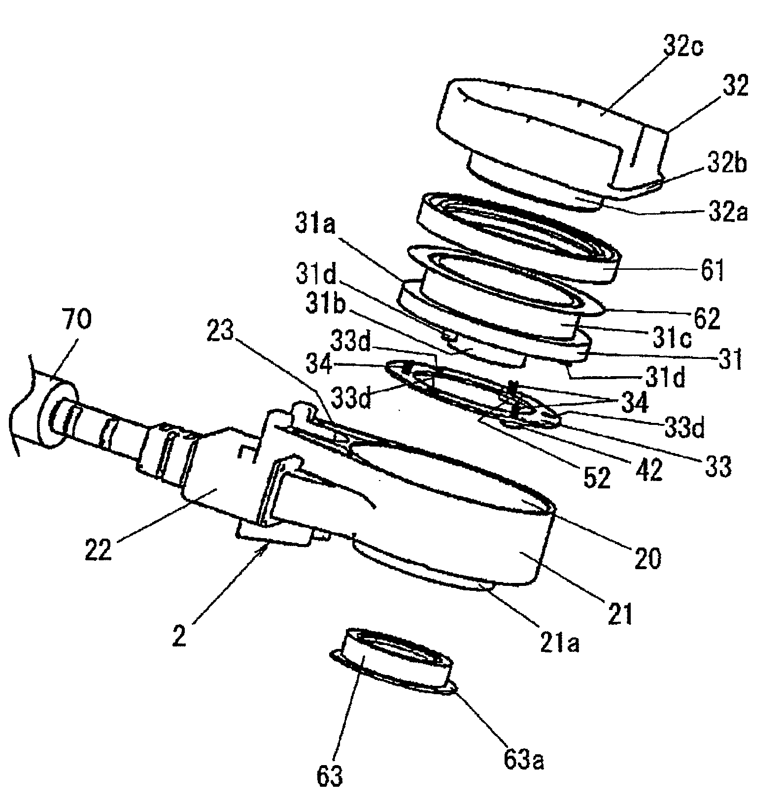
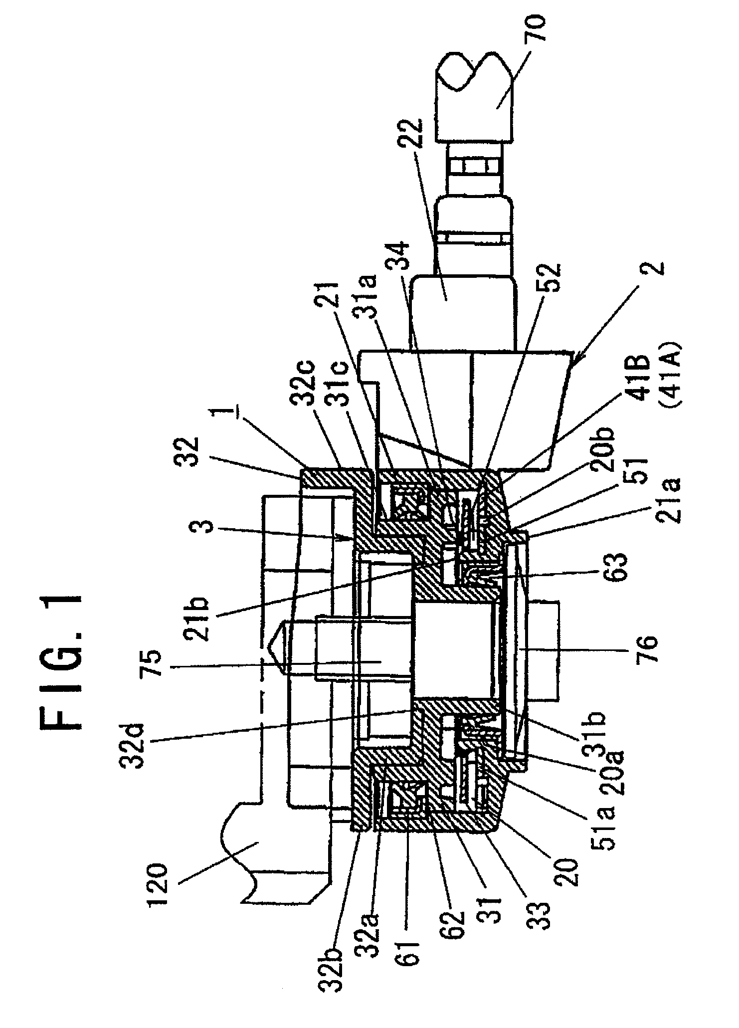
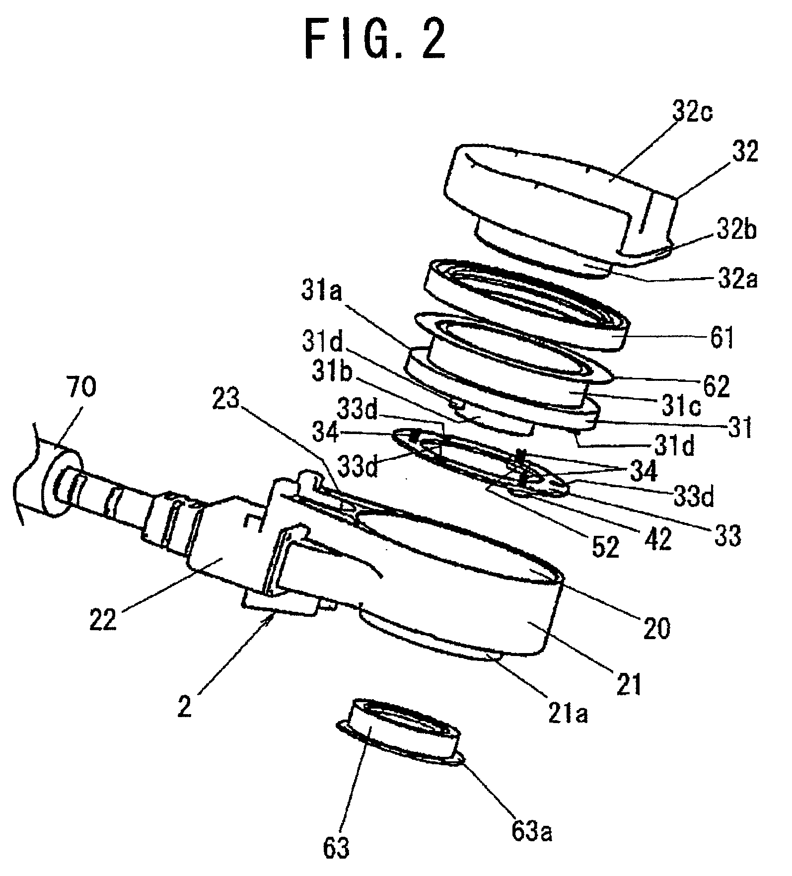
[0051]A rotary switch in accordance with a preferred embodiment of the present invention is described with reference to the drawings. FIG. 1 is a cross sectional view of a rotary switch 1 in accordance with an embodiment of the present invention and FIG. 2 is an exploded perspective view of the rotary switch 1. Hereinafter, “upward” and “downward” are described on the basis of FIG. 1.

[0052]As shown in FIGS. 1 and 2, the rotary switch 1 comprises a housing 2 and a rotor 3 which is rotatably supported on the housing 2. The housing 2 further comprises a main body 21 which has a cylindrical shape with an annular recess 20, a cable draw-out portion 22, and a holding portion 23. The rotor 3 further comprises an inner rotor 31 which is stored in the annular recess 20, an outer rotor 32 which is mechanically coupled with the inner rotor 31, a movable contact 33 which is fixed on and rotated with the inner rotor 31, and a first oil seal 61, a slide plate 62 and a second oil seal 63. The inne...


PUM


Abstract

A rotary switch, which is used to detect a state of a stand with respect to a body of a motorcycle, for example, comprises a housing having a ring-shaped outer wall so that an annular recess is formed; a rotor which is rotatably supported on the housing around a center axis of the annular recess; a plurality of stationary contacts each having a circular arc shape and provided on a bottom face of the annular recess; a moving contact which is provided on the rotor and is connected and disconnected with the stationary contacts following to rotation of the rotor with respect to the housing; and a cable draw-out portion from which an electric cable including a plurality of inner cables respectively connected to at least the stationary terminals is drawn out from the housing. The rotor has a U-shaped joint which holds an end portion of the stand pivotally mounted on the body, so that the rotor rotates corresponding to rotation of the stand with respect to the stationary portion.

Description

BACKGROUND OF THE INVENTION[0001]1. Field of the Invention[0002]The present invention relates to a rotary switch.[0003]2. Description of the Related Art[0004]Conventionally, a rotary switch, which comprises a housing with a stationary contact and a rotor with a moving contact, is provided. The moving contact, which is connected and disconnected with the stationary contact, is rotatably supported on the housing in a direction of connecting and disconnecting the moving contact with the stationary contact (Japanese Laid-Open Patent Publication No. 2004-231094, for example).[0005]For example, as shown in FIGS. 15 and 16, a rotary switch 100 having the above configuration is attached to a joint between a body 110 and a stand 120 in a motorcycle so as to detect the stand 120 stands. When the stand 120 stands during stop of the motorcycle, an engine of the motorcycle is disenabled to be started, so that it is possible too prevent the start of the motorcycle with the stand 120 standing.[000...

Claims


Application Information

Patent Timeline
Patent Type & Authority Applications(United States)
IPC IPC(8): H01H19/02
CPCB62H1/02H01H9/0264H01R13/5845H01H21/12H01H21/34H01H9/30
Inventor SAITO, TOSHIAKIIDA, NORIHIRO
Owner MATSUSHITA ELECTRIC WORKS LTD
Why Eureka
Try Eureka