Eureka AIR delivers breakthrough ideas for toughest innovation challenges, trusted by R&D personnel around the world.

Ablative Circuit Interruption Device

Inactive Publication Date: 2008-03-27
GENERAL ELECTRIC CO
View PDF9 Cites 19 Cited by
  • Summary
  • Abstract
  • Description
  • Claims
  • Application Information

AI Technical Summary

Benefits of technology

[0004]In an example embodiment, the invention includes an arc suppression insert for a circuit breaker. The insert includes an ablative body defining a chamber configured for receiving a pair of electrical contacts therein and for accommodating movement of the electrical contacts from a closed state to an open state. The chamber further includes a vent through the ablative body for venting ablation vapors produced in the chamber responsive to an electrical arc being generated between the electrical contacts when moving from the closed state to the open state effective to reduce a pressure in the chamber.
[0005]In another example embodiment, the invention includes an arc suppression insert for a circuit breaker. The insert includes an ablative body defining a chamber configured for receiving a pair of electrical contacts therein and for accommodating movement of the electrical contacts from a closed state to an open state. The chamber also includes a plurality of holes through the ablative body for venting ablation vapors produced in the chamber responsive to an electrical arc being generated between the electrical contacts when moving from the closed state to the open state effective to reduce a pressure in the chamber.
[0006]In another example embodiment, the invention includes a circuit breaker having a pair of electrical contacts and an arc suppression insert defining a chamber configured for receiving the contacts therein. The chamber is configured for accommodating movement of the contacts from a closed state to an open state. The chamber further includes a vent through the ablative body for venting ablation vapors produced in the chamber responsive to an electrical arc being generated between the electrical contacts when moving from the closed state to the open state effective to reduce a pressure in the chamber.

Problems solved by technology

The resulting ablation vapors interact with the arc to absorb the arcing energy, resulting in lower arc temperatures and dissipation of the arc.

Method used


Image

  • Ablative Circuit Interruption Device
  • Ablative Circuit Interruption Device
  • Ablative Circuit Interruption Device

Examples


Embodiment Construction

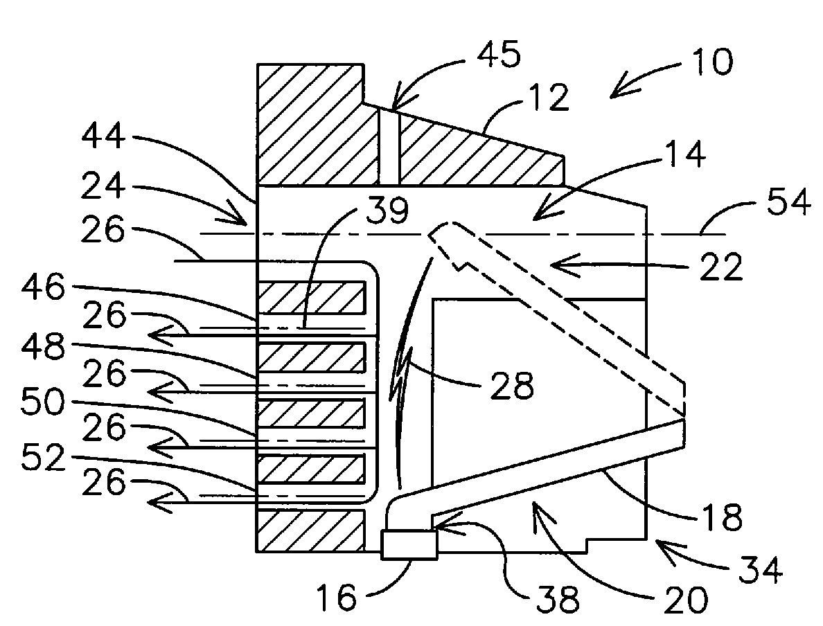
[0022]The inventors have innovatively recognized that it may be advantageous to confine an arc generated between two separating electrical contacts in arc confinement region using ablative material to achieve sufficient arc suppression, for example, without the need for an arc chute. Although the inventors have determined that arc suppression is more effective when closely confining the arc, such close confinement may produce concentrated ablative vapors in the confinement region that may limit interaction between the arc and the ablative. In addition, accumulation of ablation vapors may also result in elevated pressure in the arc confinement region. For example, it has been experimentally observed that high vapor pressures, such as vapor pressures above 100 bars, resulting from ablation in a confined region may limit arc cooling, resulting in undesirably longer arc extinguishing times. Such elevated vapor pressure may result from a choked exhaust flow condition wherein ablation vap...


PUM


Abstract

An arc suppression insert (10) for a circuit breaker (e.g., includes an ablative body (12) defining a chamber (14) configured for receiving a pair of electrical contacts (16, 18) therein. The chamber is configured for accommodating movement of the electrical contacts from a closed state (20) to an open state (22). The chamber also includes a vent (24) through the ablative body for venting ablation vapors produced in the chamber responsive to an electrical arc (28) being generated between the electrical contacts when moving from the closed state to the open state effective to reduce a pressure in the chamber.

Description

FIELD OF THE INVENTION[0001]Embodiments of the present invention are generally related to ablative circuit interruption devices, and, more particularly, to an ablative arc suppression insert comprising a vent for venting ablation vapors.BACKGROUND OF THE INVENTION[0002]A variety of devices are known for interrupting current between a source and a load. Circuit breakers are one type of device designed to trip upon occurrence of heating or over-current conditions. Such devices typically include one or more moveable contacts that separate from mating contacts to interrupt a current carrying path. The devices may be single phase or include multiple phase sections for interrupting current through parallel current paths, such as in three phase applications.[0003]Performance of a circuit interrupter is typically dictated by a peak let through current, which is in turn controlled by a rate of arc voltage development across the contacts as the contacts are moved away from one another during ...

Claims


Application Information

Patent Timeline
IPC IPC(8): H01H9/44
CPCH01H9/346H01H9/342
Inventor ASOKAN, THANGAVELUMURTHY, SUNIL SRINIVASAGORAY, KUNAL RAVINDRABOHORI, ADNAN KUTUHUDDIN
Owner GENERAL ELECTRIC CO
Why Eureka
Eureka Blog
Learn More