Spatial Frequency Wavefront Sensor System and Method

Active Publication Date: 2008-03-27
AMO MFG USA INC
View PDF36 Cites 23 Cited by
  • Summary
  • Abstract
  • Description
  • Claims
  • Application Information

AI Technical Summary

Benefits of technology

[0009] The present invention generally provides improved devices, systems, and methods for measuring and/or characterizing optical surfaces. Exemplary embodiments provide systems and methods for measuring and characterizing an optical surface of an object, such as an eye, plastic, ablated plastic, lens, spectacle or contact lens. The system often focuses and/or images light energy propagating from the object to form a pattern on a detector. The system maps the pattern with a transform function to a transform array, with the values of the array corresponding to characteristics, or signals in a transform space. For example, the pattern can be mapped to frequency space with a Fourier transform function and an intensity of spatial frequency signals stored in the array. The location and intensity of these characteristic signals along dimensions in transform space can be used to measure and/

Problems solved by technology

The known methods which determine a gradient field from several beams of light can be sensitive to errors and “noise” which can arise while finding a location of a light beam, which can

Method used


Image

  • Spatial Frequency Wavefront Sensor System and Method
  • Spatial Frequency Wavefront Sensor System and Method
  • Spatial Frequency Wavefront Sensor System and Method

Examples


Embodiment Construction

[0035] 1. Description of System and Methods

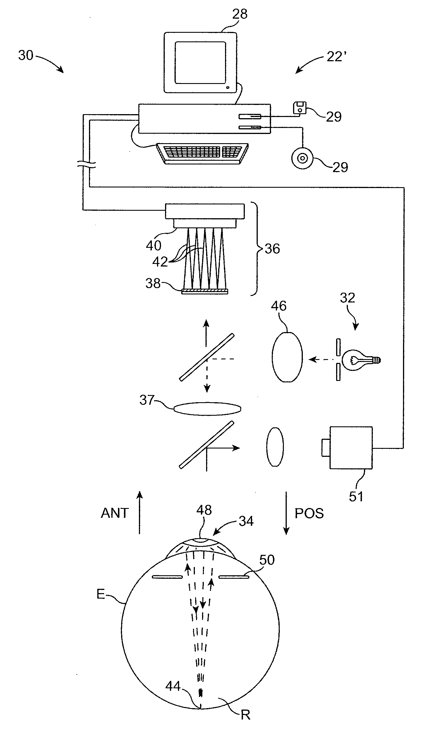
[0036] The present invention may be particularly useful for enhancing the accuracy and efficacy of laser eye surgical procedures, such as photorefractive keratectomy (PRK), phototherapeutic keratectomy (PTK), laser in situ keratomileusis (LASIK), and the like. Enhanced optical accuracy of refractive procedures may be provided by improving the methodology for deriving a corneal ablation or other refractive treatment program. Enhanced accuracy of laser system calibration prior to patient treatment may also be available by providing improved measurements of lenses ablated during system calibration. The techniques described herein can be readily adapted for use with existing laser systems, wavefront sensors, and other optical measurement devices. By providing a more direct (and hence, less prone to noise and other error) methodology for measuring and correcting errors of an optical system, these techniques may facilitate sculpting of the corne...


PUM


Abstract

Devices systems, and methods can characterize an optical surface of an object. A wavefront sensor system focuses light energy propagating from the object to form a pattern on a detector. The system maps the pattern to an array with a transform function such as a Fourier transform. The values of array correspond to characteristic locations and signals in a transform space, for example an intensity of spatial frequency signals in frequency space. The characteristic location and intensity of these signals in transform space are used to measure the optical surface. For example, a characteristic frequency of a spatial frequency intensity peak in Fourier transform space can be used to estimate the location of spots on the detector. Alternatively, the characteristics can be used to the measure sphere, cylinder and axis of a wavefront, wavefront elevation maps and point spread functions, often without locating positions of individual spots on the detector.

Description

CROSS-REFERENCES TO RELATED APPLICATIONS [0001] This is a utility patent application which claims the benefit under 35 USC 119(e) of U.S. Provisional Patent Application No. 60 / 782,679 filed Mar. 14, 2006, the full disclosure of which is incorporated herein by reference.BACKGROUND OF THE INVENTION [0002] The present invention is generally related to measurements of optical systems and surfaces. The invention provides devices, systems, and methods for measurement of optical errors of optical systems, and is particularly well-suited for determining a refractive correction of optical errors of the eye. The invention is also particularly well suited to the measurement of optical surfaces such as lenses, spectacles and contacts, including lenses ablated during calibration of a laser eye surgery system. [0003] Known laser eye surgery procedures generally employ an ultraviolet or infrared laser to remove a microscopic layer of stromal tissue from the cornea of the eye. The laser typically r...

Claims


Application Information

Patent Timeline
IPC IPC(8): G01N23/00
CPCG01M11/0264A61B3/1015
Inventor GROSS, ERIKCAMPBELL, CHARLES
Owner AMO MFG USA INC
Why Eureka
Try Eureka