Hand-held power tool

a power tool and hand-held technology, applied in the field of hand-held power tools, can solve the problems of affecting the working area of the hand-held power tool with light-emitting diodes, and the shadow cast by the insertion tool on the working area,

Inactive Publication Date: 2008-03-27
ROBERT BOSCH GMBH
View PDF10 Cites 74 Cited by
  • Summary
  • Abstract
  • Description
  • Claims
  • Application Information

AI Technical Summary

Benefits of technology

[0005]Accordingly, it is an object of the present invention to provide a hand-held power tool which eliminates the disadvantages of the prior art.

Problems solved by technology

Known hand-held power tools with light-emitting diodes do not adequately illuminate the working area, however, since the light-emitting diode is located relatively far from the working area, due to its location on the hand-held power tool.
As a result, parts of the housing and / or the insertion tool cast a shadow on the working area.

Method used


Image

  • Hand-held power tool
  • Hand-held power tool
  • Hand-held power tool

Examples


Embodiment Construction

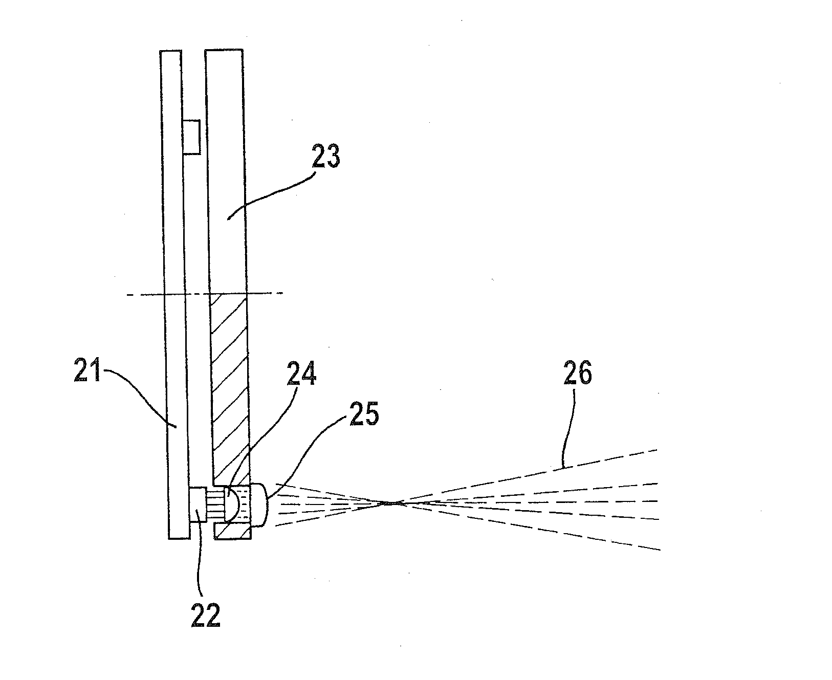
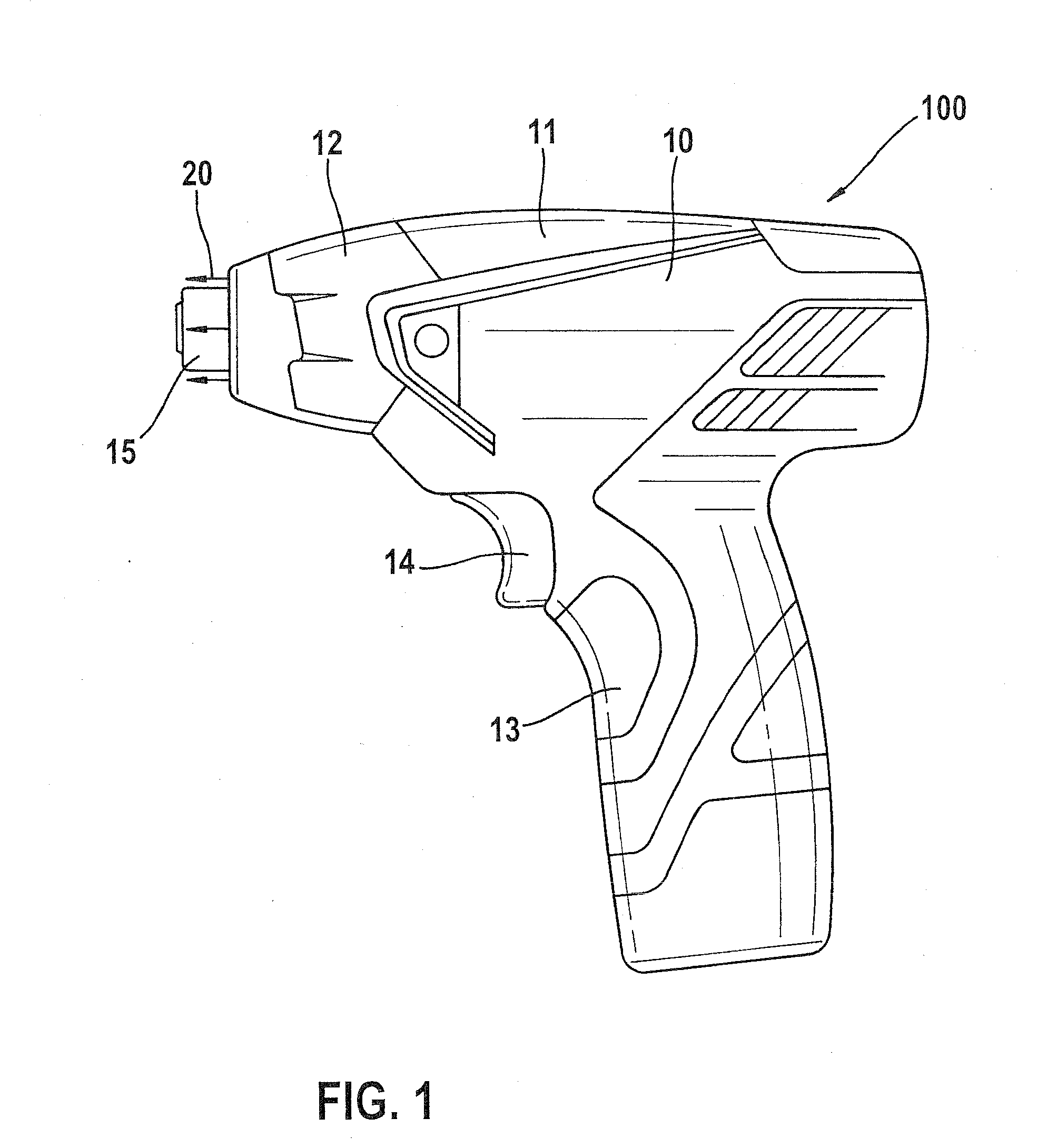
[0042]A rotary-impact wrench 100 is shown in FIG. 1, as an embodiment of an inventive hand-held power tool. Housing 10 is composed of two pieces, a motor housing 11 and a transmission housing 12. An on / off switch 14 is provided in the region of handle 13, with which an electric motor 17 (FIG. 4) is activatable. A tool fitting 15 for accommodating insertion tools, screw bits in particular, is located in the front—relative to the working direction—region of housing 10. Furthermore, the direction of radiation of light-emitting diodes is indicated in FIG. 1 via arrows 20. The light-emitting diodes are provided as illuminating elements 22 (FIG. 2) in the region of tool fitting 15. As indicated by arrows 20, illuminating elements 22 are located around the circumference of tool fitting 15.

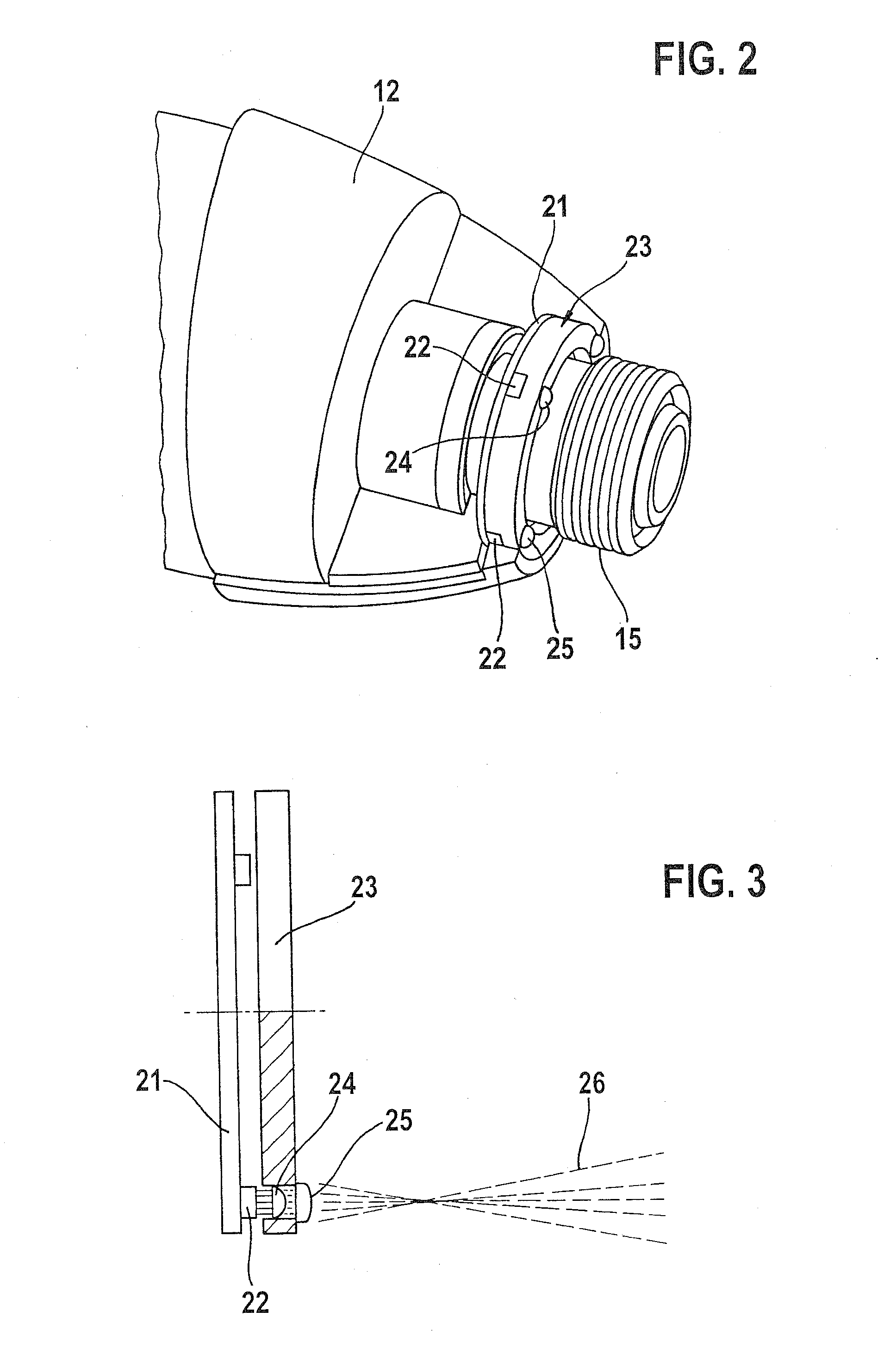
[0043]FIG. 2 shows a section of the front—relative to the working direction—region of rotary-impact wrench 100 with transmission housing 12 and tool fitting 15. Transmission housing 12 is shown in a parti...


PUM


Abstract

A hand-held power tool includes a housing with a tool fitting for receiving an insertion tool, and at least one illuminating element for illuminating the working area of the hand-held power tool; wherein the at least one illuminating element is located in the region of the tool fitting.

Description

CROSS-REFERENCE TO A RELATED APPLICATION[0001]The invention described and claimed hereinbelow is also described in German Patent Application DE 102006045157.0 filed on Sep. 25, 2006. This German Patent Application, whose subject matter is incorporated here by reference, provides the basis for a claim of priority of invention under 35 U.S.C. 119(a)-(d).BACKGROUND OF THE INVENTION[0002]The present invention relates to a hand-held power tool.[0003]Hand-held power tools are made known in the related art that are equipped with a light-emitting diode so that work can be carried out with the hand-held power tool even in poorly-lit surroundings. To this end, the light-emitting diode is located at a suitable point on the hand-held power tool, and it is oriented such that it illuminates the working area. According to DE 102 54 829 A, for example, a hollow cylindrical lamp housing is integrally formed in a lower emitting diode is formed. The opening of the lamp housing points in the direction ...

Claims


Application Information

Patent Timeline
Patent Type & Authority Applications(United States)
IPC IPC(8): B25B23/18
CPCB25F5/021B25B23/18
Inventor LUTZ, MANFREDYEOH, SIM TEIKESENWEIN, FLORIAN
Owner ROBERT BOSCH GMBH
Why Eureka
Try Eureka