Structure and manufacturing method of inversed microphone chip component

a manufacturing method and microphone chip technology, applied in piezoelectric/electrostrictive transducers, miconductor electrostatic transducers, loudspeakers, etc., can solve the problems of low reliability of microphone modules, large size of mobile phone market, and damage to microphone modules, so as to reduce the volume of modules, reduce vibration and humidity, and reduce the effect of external vibration and humidity

Active Publication Date: 2008-03-27
IND TECH RES INST
View PDF9 Cites 32 Cited by
  • Summary
  • Abstract
  • Description
  • Claims
  • Application Information

AI Technical Summary

Benefits of technology

[0028]According to the present invention, the package covers the substrate and the microphone chip, so that the microphone chip and the connection joints thereof can be well protected, accordingly the affection of external vibration and humidity can be reduced.
[0029]According to the present invention, a package is used to replace the conventional top plate and supporting ring, so that the relative process for coating inter-layer conductive compound can be skipped, and the volume of the module be greatly reduced.
[0030]Moreover, the package exposes the surface of the back acoustic cavity cover, and the surface of the package is level to the exposed surface of the back acoustic cavity cover, so that the volume of the module can be further reduced.

Problems solved by technology

Obviously, the size of mobile phone market is very large.
(1) the microphone chip is disposed within the acoustic cavity and is not protected by sealing compound, thus, the reliability of the microphone module is low, and if the microphone module falls to ground (for example, a mobile phone is dropped to the ground), the microphone module may be damaged since the solder joints of the microphone chip are not protected by sealing compound.
(2) The dispensing process is time-consuming, thus, it is difficult to increase the production throughput.
(3) The acoustic cavity is defined by stacking supporting ring and top plate, thus, the structure of the entire microphone module is not compact enough and the volume thereof cannot be reduced, and furthermore, the volume of the front acoustic cavity cannot be reduced, which results in small acoustic sensing range of the microphone module.

Method used


Image

  • Structure and manufacturing method of inversed microphone chip component
  • Structure and manufacturing method of inversed microphone chip component
  • Structure and manufacturing method of inversed microphone chip component

Examples


first embodiment

[0053]The manufacturing flow of an inversed microphone module according to the first embodiment of the present invention will be described below with reference to FIGS. 3˜11.

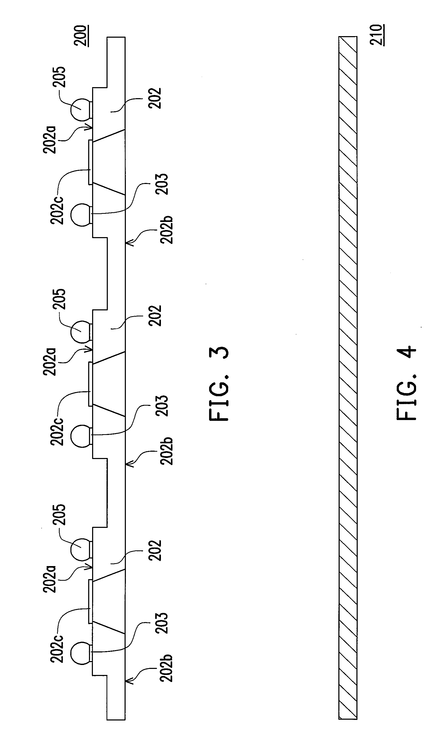
[0054]Refer to both FIG. 3 and FIG. 16, wherein FIG. 16 is a plan view of a wafer, and FIG. 3 is a side cross-sectional view of the wafer in FIG. 16.

[0055]A wafer 200 is provided. A plurality of microphone chips 202 have been formed on the surface of the wafer. Each of the microphone chips 202 has a first surface 202a and an opposite second surface 202b. A plurality of electrically bonding portions 203, for example, solder pads, and an acoustic sensing portion 202c for sensing acoustic wave are disposed on the first surface 202a are disposed on the first surface 202a.

[0056]Refer to FIG. 4 and FIG. 17, wherein FIG. 17 is a plan view of a back acoustic plate, and FIG. 4 is a side cross-sectional view of the back acoustic plate in FIG. 17.

[0057]A back acoustic plate 210 is provided. The material of the acoustic ca...

second embodiment

[0071]The difference between the second embodiment and the first embodiment is at the structures of the package 250 and the back acoustic cavity cover 212. Referring to FIG. 12, a back acoustic cavity cover 212 having a second via 215 (obtained by cutting the back acoustic plate having a via) is adopted and a predetermined mold shape is used to make the package 250 expose the surface and the second via 215 of the back acoustic cavity cover 212 and to make the surface of the package 250 to be level to the exposed surface of the back acoustic cavity cover 212.

[0072]The number of the second vias 215 is not limited herein, which may be one or more. The second vias 215 may be arranged as an array, radial, irregular, etc.

[0073]Accordingly, the volume of the microphone module can be further reduced and the acoustic sensing ability of the microphone module can be further improved.

third embodiment

[0074]In the first embodiment, a flat plate is adopted as an example of the back acoustic plate 210. However, to further enlarge the volume of the back acoustic cavity, the back acoustic plate can be made to have a predetermined roughness, such as the back acoustic plate 210′ in FIG. 19, and a plurality of protruding back acoustic cavity covers 212′ (referring to FIG. 13) can be obtained by cutting the back acoustic plate 210′.

[0075]Referring to FIG. 13, the back acoustic plate 210 in the first embodiment is replaced by the back acoustic plate 210′, the package exposes the surface of the back acoustic cavity cover 212′ and the surface of the package 250 is level to the exposed surface of the back acoustic cavity cover 212′. The volume of the back acoustic cavity becomes Vb′ which is obviously larger than the volume V2 of the conventional back acoustic cavity (referring to FIG. 2).

[0076]A back acoustic cavity cover having a via may also be adopted as in the second embodiment, and the...


PUM


Abstract

An inversed microphone module is provided. The module includes a substrate, a microphone chip, a back acoustic cavity cover, and a sealing material. The substrate has a plurality of connection pads and an acoustic hole. The microphone chip has a first surface and an opposite second surface. A plurality of electrically bonding portions and an acoustic sensing are disposed on the first surface. The microphone chip is electrically coupled to the connection pads of the substrate through the electrically bonding portions, and the acoustic hole corresponds to the acoustic sensing portion. The back acoustic cavity cover is fixed to the second surface and defines a back acoustic cavity with the acoustic sensing portion and the microphone chip. The sealing material encapsulates the microphone chip and covers the substrate, so that the sealing material, the substrate, the acoustic sensing portion, and the first surface define a front acoustic cavity.

Description

CROSS-REFERENCE TO RELATED APPLICATION[0001]This application claims the priority benefit of Taiwan application serial no. 95133255, filed Sep. 8, 2006. All disclosure of the Taiwan application is incorporated herein by reference.BACKGROUND OF THE INVENTION[0002]1. Field of the Invention[0003]The present invention relates to a structure and a manufacturing method of an inversed microphone module and a microphone chip component.[0004]2. Description of Related Art[0005]Along with the personalization and popularization of global communication, it has become very common that everybody has at least one mobile phone. Due to the requirement of parenthood, even school children have mobile phones, thus, the age of mobile phone's consumer group is greatly reduced to be below 10.[0006]Moreover, according to a report issued by Topology Research Institute (TRI) in September, 2005, global production of mobile phones in 2005 is about 760 millions, and the number of mobile phone users is up to 1.685...

Claims


Application Information

Patent Timeline
Patent Type & Authority Applications(United States)
IPC IPC(8): H04R25/00
CPCB81B7/0061B81B2201/0257H04R1/2819H04R2499/11H04R19/04H04R31/006H04R2201/003H04R19/005H01L2224/48091H01L2224/48227H01L2224/8592H01L2924/10155H01L2924/15151H01L2924/16151H01L2924/16195H01L2924/00014
Inventor CHEN, JUNG-TAICHU, CHUN-HSUN
Owner IND TECH RES INST
Why Eureka
Try Eureka