Method of handling radio link failure in wireless communications system and related device

a wireless communication system and radio link technology, applied in the direction of connection management, transmission, transmission system, etc., can solve the problems of limiting the efficiency of ue capability, radio link failure, and radio link failure between user equipment (ue) and utran

Inactive Publication Date: 2008-03-27
INNOVATIVE SONIC
View PDF14 Cites 34 Cited by
  • Summary
  • Abstract
  • Description
  • Claims
  • Application Information

AI Technical Summary

Benefits of technology

[0018]According to the present invention, a communications device capable of detecting radio link failure (RLF) for use in a wireless communications system comprises a control circuit for realizing functions of the communications device, a processor installed in the control circuit, for executing a program code to operate the control circuit, and a memory coupled to the processor for storing the program code. The program code comprises code for a user equipment (UE) performing action(s) if an indication is received from a network entity for action rule(s) and / or trigger(s) to enter a radio state, and code for the user equipment entering the radio state or remaining in the radio state.

Problems solved by technology

In a wireless communications system, radio link failure (RLF) between user equipment (UE) and UTRAN can occur due to all kinds of impairments in a wireless environment, unfavorable signal propagation conditions, or even system malfunctions.
Therefore, it is possible that radio link failure will happen in one frequency layer, and the other frequency layer (or other frequency layers in case of multiple receiver) will maintain good radio link condition.
Therefore, there is no reason to maintain only one timer that may limit the efficiency of UE capability and be unfair to different service requirements.
However, LTE removes the RNC, so that it is unclear which entity should decide the configuration values of the timers.
Similar to the problem of the prior art mentioned above, it remains unclear how many timers and parameters are used to detect or handle the radio link failure, and how those values are configured in LTE.

Method used


Image

  • Method of handling radio link failure in wireless communications system and related device
  • Method of handling radio link failure in wireless communications system and related device
  • Method of handling radio link failure in wireless communications system and related device

Examples


Embodiment Construction

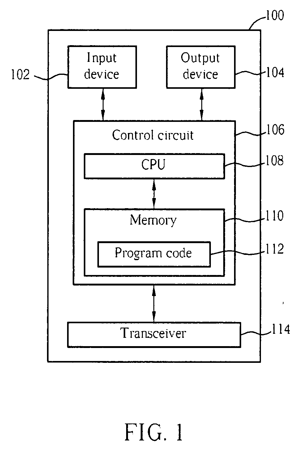
[0023]Please refer to FIG. 1, which is a functional block diagram of a communications device 100. For the sake of brevity, FIG. 1 only shows an input device 102, an output device 104, a control circuit 106, a central processing unit (CPU) 108, a memory 110, a program code 112, and a transceiver 114 of the communications device 100.

[0024]In the communications device 100, the control circuit 106 executes the program code 112 in the memory 110 through the CPU 108, thereby controlling an operation of the communications device 100. The communications device 100 can receive signals input by a user through the input device 102, such as a keyboard, and can output images and sounds through the output device 104, such as a monitor or speakers. The transceiver 114 is used to receive and transmit wireless signals, delivering received signals to the control circuit106, and outputting signals generated by the control circuit 106 wirelessly. From a perspective of a communications protocol framewor...


PUM


Abstract

Handling radio link failure efficiently in a packet switching domain of a wireless communications system includes a user equipment performing an action when an indication is received from a network entity for an action rule or action rules and a trigger or triggers to enter a radio state, and the user equipment entering the radio state.

Description

CROSS REFERENCE TO RELATED APPLICATIONS[0001]This application claims the benefit of U.S. Provisional Application No. 60 / 846,102, filed on Sep. 21, 2006 and entitled “Method and Apparatus for Handling Radio Link Failure in Wireless Communications System,” the contents of which are incorporated herein by reference.BACKGROUND OF THE INVENTION[0002]1. Field of the Invention[0003]The present invention relates to methods of handling radio link failure in wireless communications systems and related devices, and more particularly, to a method and related device for entering a radio state after radio link failure is detected.[0004]2. Description of the Prior Art[0005]In a wireless communications system, radio link failure (RLF) between user equipment (UE) and UTRAN can occur due to all kinds of impairments in a wireless environment, unfavorable signal propagation conditions, or even system malfunctions. For some applications, upon RLF, a user may notice immediately if there is unexpected del...

Claims


Application Information

Patent Timeline
Patent Type & Authority Applications(United States)
IPC IPC(8): G01R31/08H04Q7/20H04W76/02
CPCH04W76/028H04W76/19H04W76/18H04W76/27
Inventor JEN, YU-CHIN
Owner INNOVATIVE SONIC
Why Eureka
Try Eureka