
Vortex feature for drug delivery system

a technology of drug delivery system and valve, which is applied in the field of automatic injector, can solve the problems of shortening the time needed to administer a dose of the therapeutic agent, affecting the safety of patients, and long-term storage of the therapeutic agent as a liquid solution, so as to improve the mixing ability, improve the mixing effect of the liquid component and the dry component, and improve the mixing

Active Publication Date: 2008-03-27
MERIDIAN MEDICAL TECH
View PDF29 Cites 9 Cited by
  • Summary
  • Abstract
  • Description
  • Claims
  • Application Information

AI Technical Summary

Benefits of technology

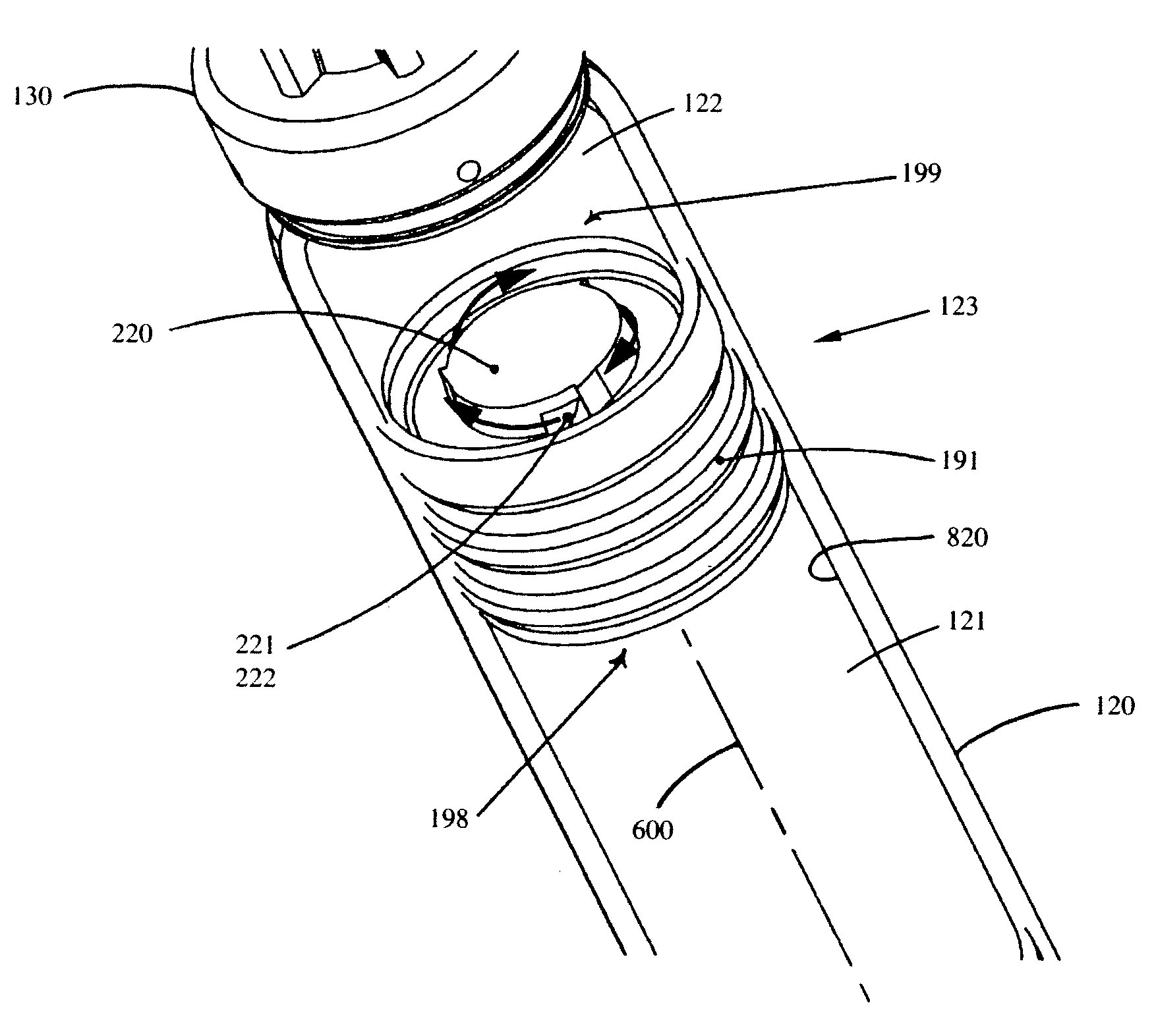
[0006] The invention is directed to wet / dry automatic injectors having improved mixing capabilities. By introducing a “fluid-directing member” that causes the liquid component to form a vortex, mixing of the liquid component with the dry component is improved, including improved dissolution of the dry component into the liquid component. The vortical flow has axial, radial, and circumferential components that improve mixing. As a result, a greater amount of the dry component is dissolved in the liquid component in a shorter period of time, thus allowing the user to get a more immediate, effective dose of a therapeutic agent. Moreover, increased amounts of the dry component are ultimately delivered as compared to currently available systems.
[0010] The fluid-directing member has at least one channel that has a fluid exit port with an opening into the dry compartment that fully faces the inner side surface of the chamber. In other words, the opening does not face forward (i.e., towards the needle assembly), but instead faces the side wall of the chamber. The channel is preferably helically shaped about the central longitudinal axis and is in fluid communication with the flow path of the seal structure. The channel is also preferably oriented at an angle ranging from about 80° to 90° with respect to the longitudinal axis of the housing assembly. The fluid-directing member may have a plurality of channels. For example, respective embodiments of the fluid-directing member may have one, two, three, or four helical channels. In preferred embodiments, the channels are separate; however, a fluid-directing member alternatively may have interconnected channels. Each channel preferably has at least one fluid exit port, and multiple fluid exit ports are arranged preferably equidistantly radially around the central longitudinal axis. The channels may be of shapes other than helical, provided that those shapes give the liquid component a substantial circumferential flow component and / or allow the liquid component to form a vortex within the dry compartment. For example, the channels may be circular, linear, inclined, helical, or a combination thereof. Additionally, multiple channels in the same fluid-directing member can each be of the same or similar shape or, alternatively, of different shapes. In preferred embodiments, the channels direct most if not all of the fluid into the dry compartment at angles ranging from about 80° to 90° with respect to the central longitudinal axis of the housing assembly. This facilitates formation of a vortex in the dry compartment. Optionally, the channels can be constructed to direct fluid into the dry compartment at angles ranging from about 10° to 90°.

Problems solved by technology

However, the long-term storage of a therapeutic agent as a liquid solution has drawbacks.
For instance, some therapeutic agents are not stable in solution and thus have a shorter shelf-life than their solid counterparts.
Unfortunately, steps such as manually shaking the injector increase the time needed to administer a dose of the therapeutic agent, which is undesirable in many emergency medical situations where rapid delivery of the therapeutic agent is needed (e.g., nerve gas and chemical agent poisoning).

Method used


Image

  • Vortex feature for drug delivery system
  • Vortex feature for drug delivery system
  • Vortex feature for drug delivery system

Examples


examples

[0045] The results shown in Tables 1 and 2 below demonstrate the improved mixing and dissolution capabilities of the fluid-directing member of the invention.

[0046] Table 1 shows test results of administering a dry component mixed with a liquid component using an auto-injector with a fluid-directing member. Table 2 shows test results of administering a dry component mixed with a liquid component using an auto-injector without a fluid-directing member.

[0047] The tests were done by first loading a sample of a dry component into a wet / dry auto-injector. The auto-injector was then activated, allowing the liquid component to mix with the dry component before being dispensed. The dispensed sample was collected in a container and the dispensed sample and container were weighed. The liquid component was then removed and the dry component and container were weighed. The dispensed solid mass was determined. Also, the mixing / dispensing time was measured.

TABLE 1Devices with Fluid-Directing M...


PUM


Abstract

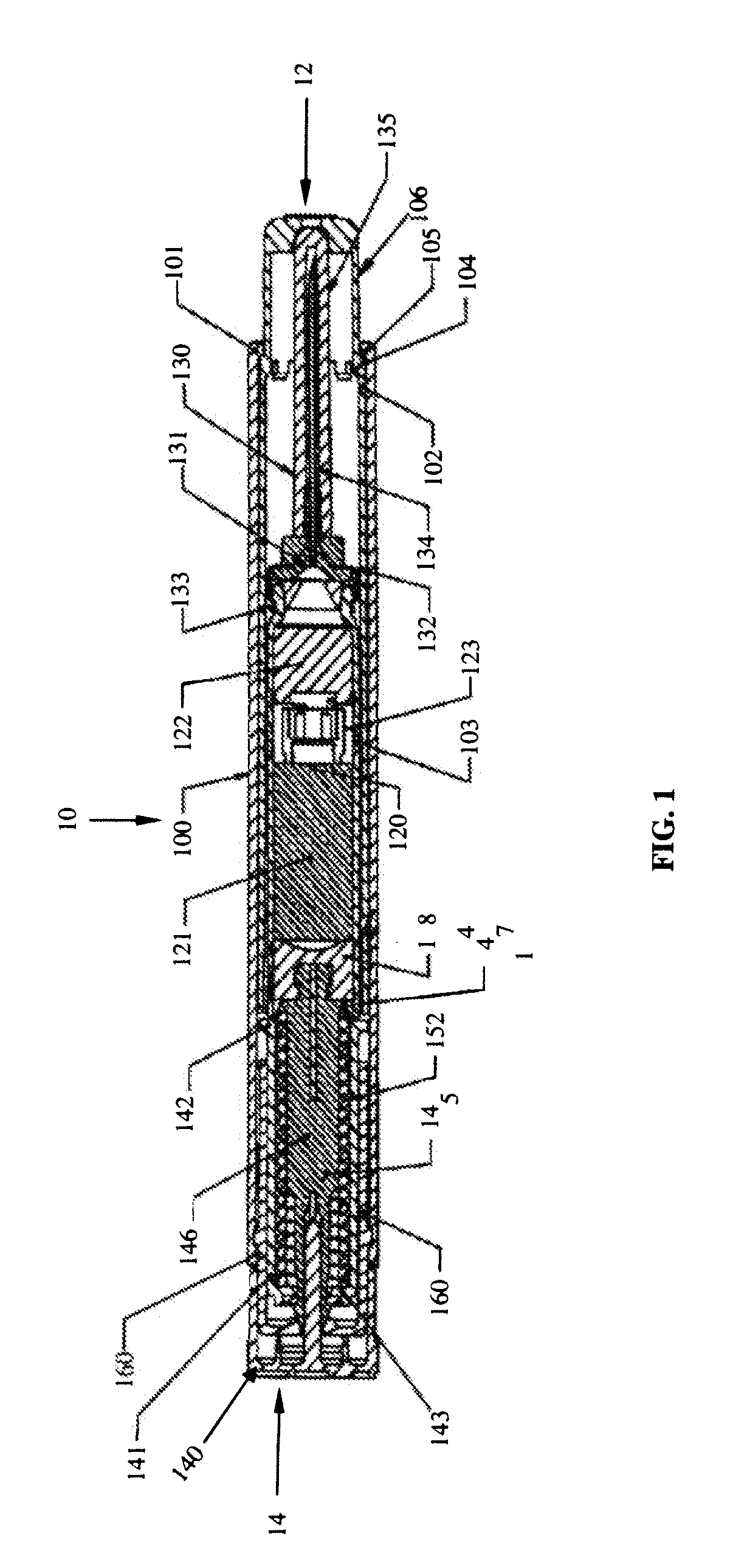
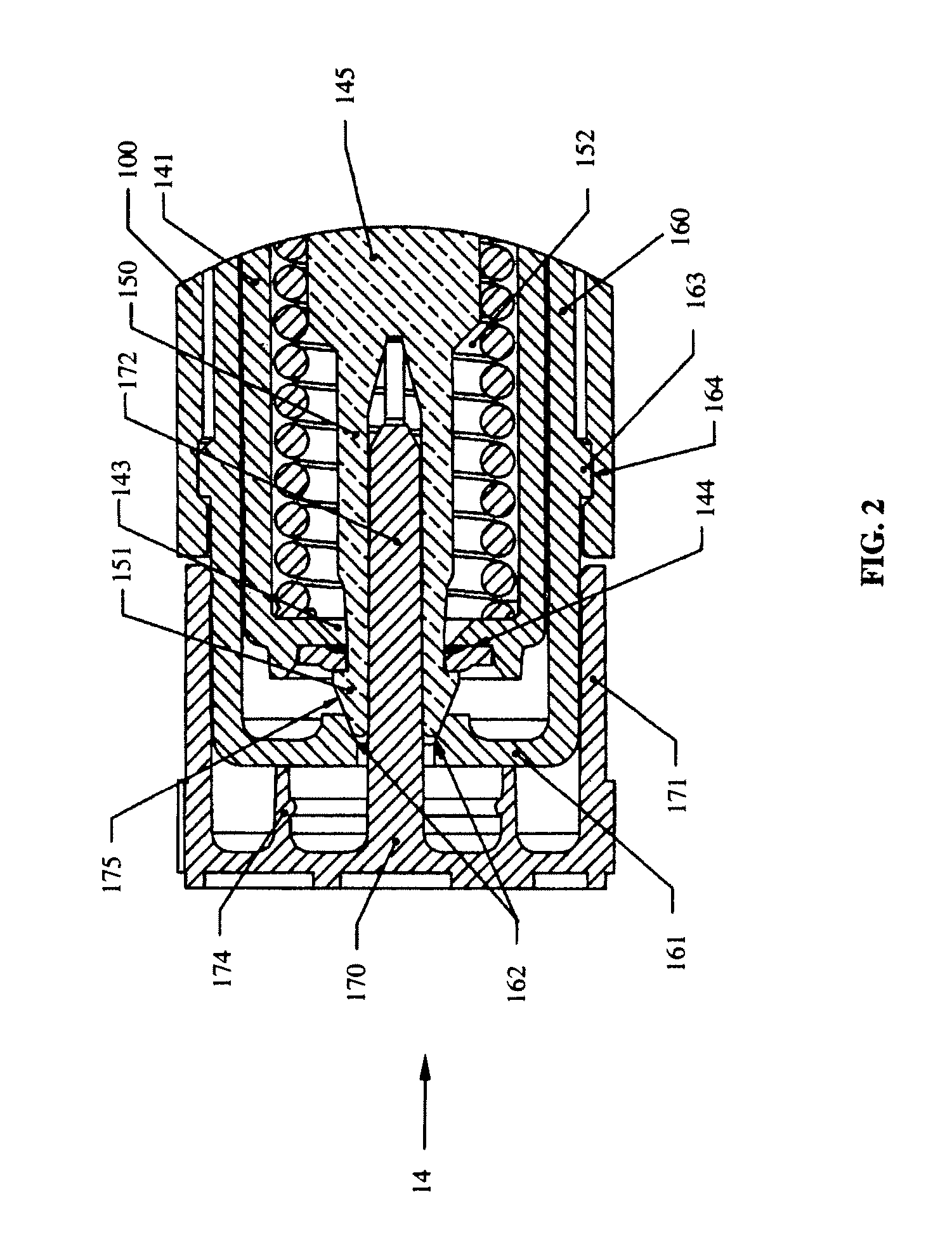
An automatic injector separately stores liquid and dry components in respective compartments. When the injector is activated, a fluid-directing member between the liquid and dry compartments causes the liquid component to form a vortex as the liquid flows into the dry compartment. This allows the two components to combine more thoroughly and quickly to form a liquid solution that is delivered to an injection site.

Description

CROSS REFERENCE TO RELATED APPLICATION [0001] This claims the benefit of U.S. Provisional Application No. 60 / 841,709, filed Aug. 31, 2006, the entire contents of which are incorporated herein by reference thereto.FIELD OF THE INVENTION [0002] The invention relates to drug delivery devices that deliver therapeutic agents. More particularly, the invention is directed to an automatic injector that quickly combines two components to form a liquid therapeutic agent delivered to an injection site. BACKGROUND OF THE INVENTION [0003] An automatic injector is a device that enables intramuscular or subcutaneous administration of a therapeutic agent. An advantage of automatic injectors is that they contain a measured dose of a therapeutic agent in a sealed sterile cartridge. As such, automatic injectors can be used in emergency situations to quickly and simply inject the therapeutic agent without having to measure dosages. Another advantage of automatic injectors is that the administration of ...

Claims


Application Information

Patent Timeline
IPC IPC(8): A61M5/19
CPCA61M5/2033A61M5/2066A61M2005/2073A61M2005/2013A61M2005/206A61M5/31596
Inventor GRIFFITHS, STEVEN M.HILL, ROBERT L.ROBBEN, MATTHEW P.
Owner MERIDIAN MEDICAL TECH
Learn More