Rod inserter and rod with reduced diameter end

a technology of rod inserter and rod end, which is applied in the field of spinal stabilization system, can solve the problems of reducing patient recovery time, affecting patient recovery, and affecting patient recovery, and achieves the effect of facilitating percutaneous spinal rod insertion and accelerating patient recovery

Active Publication Date: 2008-03-27
STRYKER EURO OPERATIONS HLDG LLC
View PDF99 Cites 115 Cited by
  • Summary
  • Abstract
  • Description
  • Claims
  • Application Information

AI Technical Summary

Benefits of technology

[0029]Although the present invention is not limited by any particular theory of operation, it is believed that providing an inserter toll for a spinal rod as disclosed herein enables polyaxial adjustability of the orientation of the spinal rod within the rod inserter tool to acc

Problems solved by technology

Patients that suffer from such conditions usually experience extreme and debilitating pain as well as diminished nerve function.
However, as will be set forth in more detail below, there are some disadvantages associated with current fixation devices.
Surgeons have frequently encountered considerable difficulty when attempting to insert spinal fixation devices such as those disclosed in the above-mentioned '388 patent.
For e

Method used


Image

  • Rod inserter and rod with reduced diameter end
  • Rod inserter and rod with reduced diameter end
  • Rod inserter and rod with reduced diameter end

Examples


Embodiment Construction

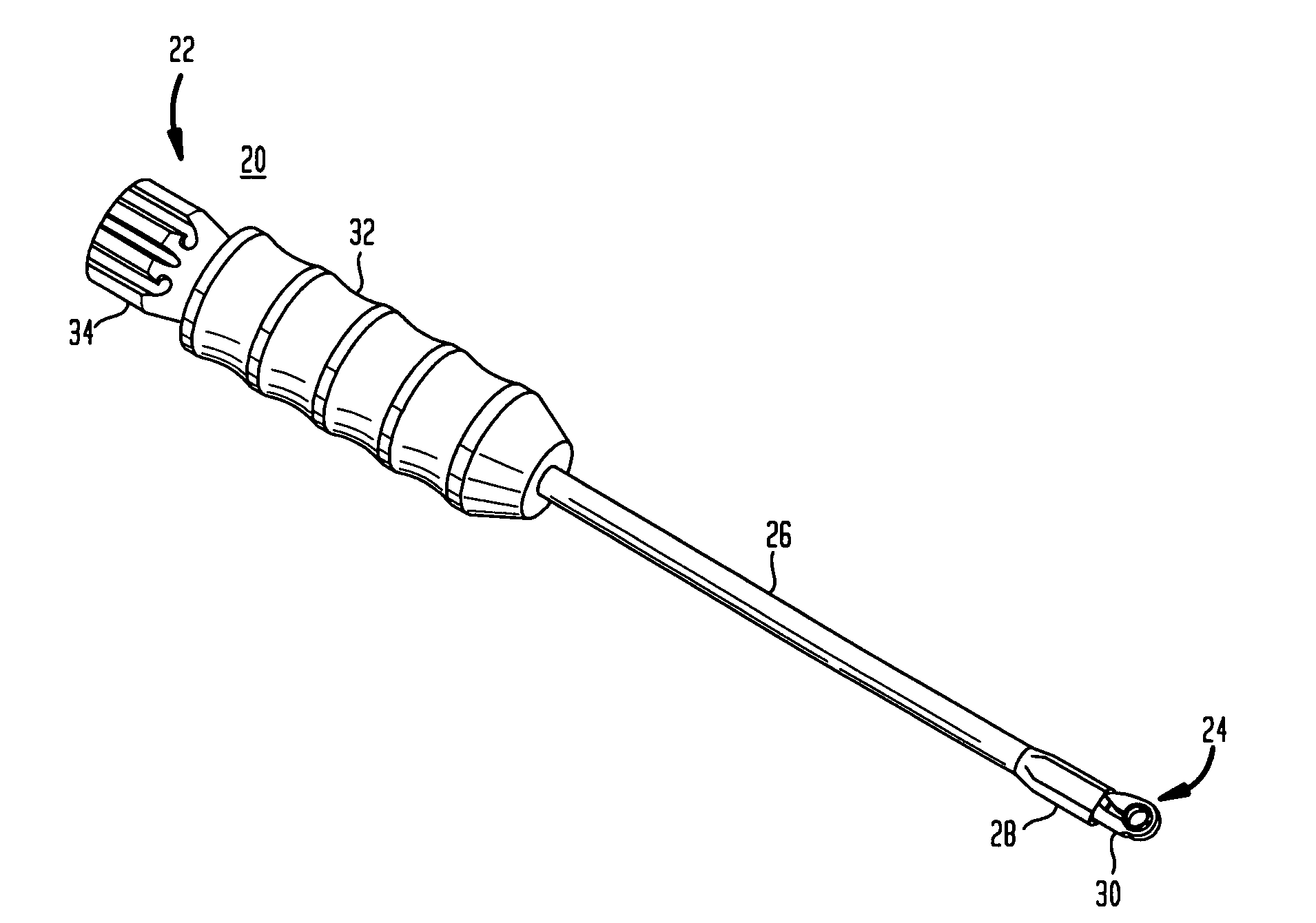
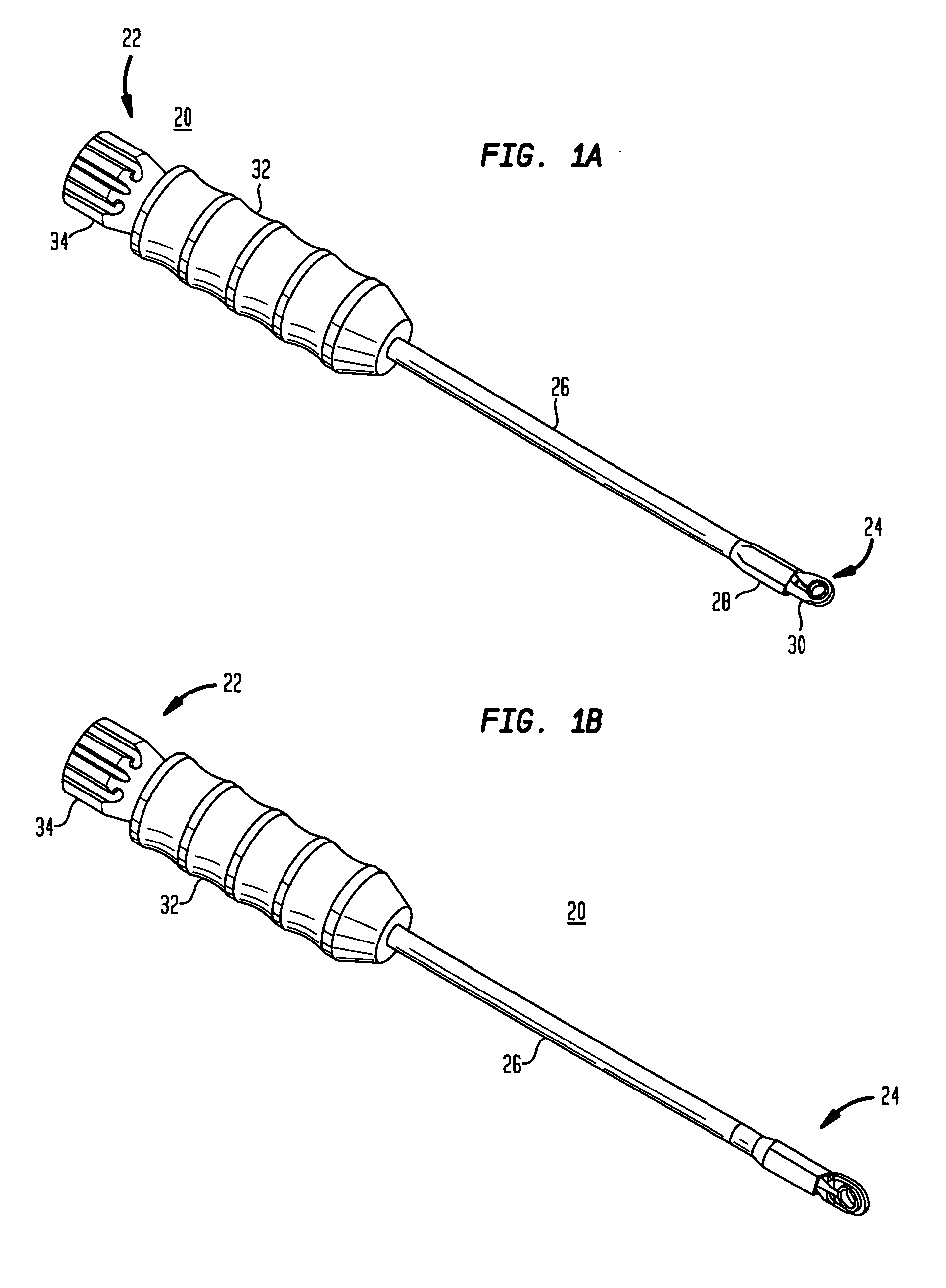
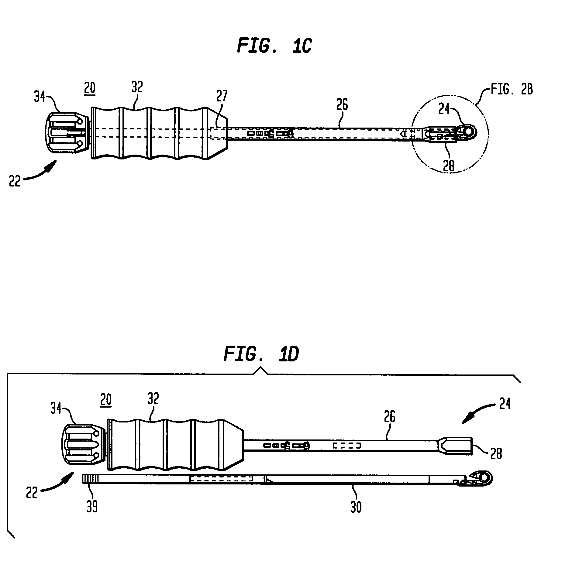
[0041]Referring to FIGS. 1A-1D, in certain preferred embodiments of the present invention, a rod inserter 20 has a proximal end 22 and a distal end 24 remote therefrom. The rod inserter 20 includes an outer shaft 26 having an elongated or longitudinally extending opening that extends from a proximal end 27 to a distal end 28 thereof. The rod inserter 20 also includes an inner shaft 30 (FIG. 1D) that is telescopically received within the outer shaft 26. The rod inserter 20 includes a handle 32 secured to the proximal end 27 of the outer shaft 26. The handle 32 is preferably secured to the outer shaft 26 so that the outer shaft is incapable of moving axially or rotationally relative to the handle 32. The rod inserter 20 also preferably includes a rotatable knob 34 that is rotated in a first direction for moving the inner shaft 30 axially toward the proximal end of the inserter tool and relative to the outer shaft 26, and in a second direction for retracting the inner shaft 30 into the...


PUM


Abstract

An inserter tool for coupling a spinal rod with an implant includes an outer shaft having a proximal end, a distal end and an elongated opening extending between the proximal and distal ends, a handle secured to the proximal end of the outer shaft, and an inner shaft having a proximal end and a distal end, the inner shaft being telescopically received within the elongated opening of the outer shaft and being adapted to move between the proximal and distal ends of the outer shaft. The tool includes a compressible clamping tip secured to the distal end of the inner shaft, the clamping tip including a first section secured to the distal end of the inner shaft, a flexible arm that extends from the first section, and an opening disposed between the first section and the flexible arm. A knob is coupled with the proximal end of the inner shaft, the knob being rotatable in a first direction for extending the clamping tip from the distal end of the outer shaft and in a second direction for retracting the clamping tip into the distal end of the outer shaft so as to compress the flexible arm of the clamping tip toward the first section of the clamping tip.

Description

CROSS-REFERENCE TO RELATED APPLICATIONS[0001]The present application claims the benefit of U.S. Provisional Application Ser. No. 60 / 847,009, filed Sep. 25, 2006, the disclosure of which is hereby incorporated by reference herein. The present application is related to U.S. patent application Ser. No. 11 / 526,785, entitled, “Rod Contouring Apparatus and Method for Percutaneous Pedicle Screw Extension,” filed Sep. 25, 2006, which claims the benefit of U.S. Provisional Application No. 60 / 765,606, filed Feb. 6, 2006, the disclosures of which are hereby incorporated by reference herein.BACKGROUND OF THE INVENTION[0002]The present invention generally relates to spinal stabilization systems and more specifically relates to pedicle screw assemblies and tooling used with pedicle screw assemblies.[0003]The spinal column is a highly complex system of bones and connective tissues that provides support for the body and protects the delicate spinal column and nerves. The spinal column includes a se...

Claims


Application Information

Patent Timeline
IPC IPC(8): A61B17/56
CPCA61B17/7004A61B17/7085A61B17/7083A61B17/7011
Inventor TRIPLETT, DANIELFALLIN, T. WADEMOHR, KARENMILLARD, THIERRY
Owner STRYKER EURO OPERATIONS HLDG LLC
Why Eureka
Try Eureka